
Specifications


EXB-REL8
36
ICSLan Device Control Boxes
Connections and Wiring
LAN/PoE Port (RJ45)
The LAN/PoE (RJ45) port on the rear panel provides 10/100 BaseT network connectivity. This port is
common to all EXB Modules. Use standard Cat5/6/6E ethernet cable to connect the EXB Module to the LAN.
Refer to the LAN/PoE Port section on page 7 for the pinout configuration for this port.
Port 1 (Relay Connector)
The Relay Connectors on the rear panel are two 8-pin 3.5mm captive-wire connectors that provide A and B
connections for eight SPST Relay channels (1-8).
Connectors labeled A for Common, B for Output.
These relays are independently controlled, isolated and normally open.
The relay contacts are rated for a maximum of 1 A @ 0-24 VAC or 0-28 VDC (resistive).
NetLinx Programming
EXB-REL8 Port Assignments
EXB-REL8 Channel Assignments
EXB-REL8 SEND_COMMANDs
The following NetLinx SEND_COMMANDs are supported by the EXB-REL8 Module:
Telnet commands
Refer to the Terminal (Telnet) Commands section on page 53 for a listing of all supported Telnet commands.
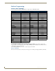
Relay Connector Pinouts
First Relay Connector Pinout Second Relay Connector Pinout
Pin Description Pin Description
1 Channel 1A 1 Channel 5A
2 Channel 1B 2 Channel 5B
3 Channel 2A 3 Channel 6A
4 Channel 2B 4 Channel 6B
5 Channel 3A 5 Channel 7A
6 Channel 3B 6 Channel 7B
7 Channel 4A 7 Channel 8A
8 Channel 4B 8 Channel 8B
An 8-position metal Commoning Strip (41-2105-01) is provided with each EXB-REL8
to common multiple relays.
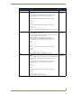
EXB-REL8 Port Assignments
Port Description
1 All Relays (channels 1-8)
EXB-REL8 Channel Assignments
Channel Description
1-8 Channels 1-8 represent Relays 1-8.
EXB-REL8 SEND_COMMANDs
Command Page Reference Command Page Reference
LED-DIS page 42 REBOOT page 44
LED-EN page 42 SET_NDX_DESC page 47