
Specifications


EXB-MP1
31
ICSLan Device Control Boxes
EXB-MP1
Overview
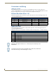
The EXB-MP1Networked Television Control System Device (FG2100-26) provides one Serial (RS-232) port,
one I/O port, one IR (TX) and one IR (RX) port (FIG. 9).
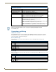
EXB-MP1 Product Specifications
In addition to the features described in the ICSLan Device Control Boxes - Common Features table on page 2,
the components and specifications listed below are specific to the EXB-MP1 module:
FIG. 9 EXB-MP1
EXB-MP1 Specifications
Power Requirements
PoE (Power-over-Ethernet)
Power Draw • Idle (min): 40mA 1.92 watts
• Busy (max): 40mA 1.92 watts
Front Panel Components
Ethernet / PoE Connector RJ-45 connector provides TCP/IP communication and PoE.
This is an Auto MDI/MDI-X enabled port, therefore either straight-through or
crossover Ethernet cables can be used.
232 TX/RX LEDs 2 LEDs light to indicate incoming (RX- yellow) and outgoing (TX - red) activity
on the Serial port (Port 1).
I/O (1 & 2) LEDs 2 (yellow) LEDs light to indicate which channels (1-2) are active (output high)
on the I/O port (Port 2).
IR TX/RX LEDs 2 LEDs light to indicate incoming (RX - yellow) and outgoing (TX - red) activity
on the IR Port.
• Port 3 = IR Transmit (TX)
• Port 4 = IR Receive (RX)
(front)
(rear)
LINK/ACT LED
STATUS LED
Ethernet Port (RJ-45)
PORT 2 (I/O)
ID Pushbutton
PORT 1
Port 1 (RS232) TX/RX LEDs
Port 2 (I/O) TX/RX LEDs
Port 3/4 (IR) TX/RX LEDs
PORT 3 (IR-TX)
PORT 4 (IR-RX)
(RS-232 only)