
Specifications


EXB-IRS4
28
ICSLan Device Control Boxes
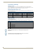
Linked Modes
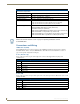
The following table describes the four linking modes on the EXB-IRS4:
IO-Linked Modes
Unlinked
(default)
• Exited by SET INPUT LINK <port> (see SET INPUT LINK on page 46)
• LEDs reflect the power state of the 4 input pins
• Channel 255 reports the power state of the 4 input pins on their default port#
• All POD (page 42), PON (page 43), POF (page 43) messages are ignored
• No IR activity due to pin state
POD
(default linked state)
In POD state, the PON/POF behavior is disabled and the state of the input pin is not
used to trigger the sending of power on/off pulses. This is the default state of a linked
port upon receiving the “SET INPUT LINK” command.
• Exited by PON (page 43), POF (page 43), or SET INPUT LINK 0 (page 46)
• LEDs reflect the power state of the 4 input pins
• Channel 255 reports the power state of the 4 input pins on their linked port#(s)
• PON, POF messages are applied
• No IR activity due to pin state
PON In the PON state, the IR/SERIAL port is used to keep the TV powered on.
When in PON state, if the TV is sensed via the input pin to be off, power-on pulses are
sent out the IR/SERIAL port until the TV is sensed to be on.
• Exited by POD (page 42), POF (page 43), or SET INPUT LINK 0 (page 46)
• LEDs reflect the power state of the 4 input pins
• Channel 255 reports the power state of the 4 input pins on their linked port#(s)
• POD, POF messages are applied
• IR activity to maintain power ON pin state
Note: When an IR/SERIAL port is linked and in PON state, the time delay set by the
PTON Send Command (see page 44) is used for power pulses sent out the port.
POF In the POF state, the IR/SERIAL port is used to keep the TV powered off.
When in POF state, if the TV is sensed via the input pin to be on, power-off pulses are
sent out the IR/SERIAL port until the TV is sensed to be off.
• Exited by PON (page 43), POD (page 42), or SET INPUT LINK 0 (page 46)
• LEDs reflect the power state of the 4 input pins
• Channel 255 reports the power state of the 4 input pins on their linked port#(s)
• POD, PON messages are applied
• IR activity to maintain power OFF pin state
Note: When an IR/SERIAL port is linked and in POF state, the time delay set by the
PTOF Send Command (see page 44) is used for power pulses sent out the port.