
Specifications


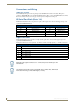


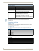

EXB-IRS4
27
ICSLan Device Control Boxes
Input Linking
The EXB-IRS4 has 4 IR-Tx ports (labelled "IR/SERIAL") and 4 associated input pins. Each of the 4 input pins
is directly associated with one IR-Tx port. Port #1 is associated with input pin #1 and so on.
Any of the 4 IR-Tx ports/pins on an EXB-IRS4 can be run in either “unlinked” or “linked” mode:
Unlinked Mode (Default)
Unlinked mode is the default mode at boot up. When an IR/SERIAL port is unlinked the input pin state has no
effect on the IR-Tx port.
Linked Mode
Linked mode is intended to provide the function of a “light switch” for the power state of a television via the
EXB-IRS4’s IR interface.
When a port is linked, the power state (on/off) of the TV is sensed via the input pin and factored into the logic
of whether or not to send power on/off IR pulses out the port to the TV. In this way, even a TV with a simple
power toggle IR code can be reliably turned on and off by the EXB-IRS4.
When in linked mode, the IR/SERIAL port is in one of 3 mutually exclusive states: POD, PON or POF (see
the IO-Linked Modes table on page 28).
Input Pin
The firmware on the EXB-IRS4 senses the high/low state of the pin and always reports that state to the master
via PUSH/RELEASE messages on ports 1-4 channel 255. This behavior persists regardless of whether the pin
is linked or unlinked.
Entering/Exiting Linked Mode
Linked mode is entered by sending the “SET INPUT LINK” command (see page 46) to a specific [D:P:S].
The EXB-IRS4 firmware will accept a port number from 1 to 4 and will enable linked mode on that port.