
Specifications


EXB-COM2
18
ICSLan Device Control Boxes
Connections and Wiring
LAN/PoE Port (RJ45)
The LAN/PoE (RJ45) port on the rear panel provides 10/100 BaseT network connectivity. This port is
common to all EXB Modules. Use standard Cat5/6/6E ethernet cable to connect the EXB Module to the LAN.
Refer to the LAN/PoE Port section on page 7 for the pinout configuration for this port.
Port 1(Multi-Protocol COM Port)
Port 1 (multi-protocol port) on the rear panel is a 10-pin 3.5mm captive-wire connector that supports
RS-232/422/485 serial communication. The following table describes the pinout configuration of Port 1:
Port 2 (RS-232 only)
Port 2 on the rear panel is a 5-pin 3.5mm captive-wire connector that supports RS-232 (only) serial
communication. Pins 1-5 on COM2 provide the same RS-232 functions as pins 1-5 on the COM1 connector:
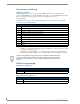
EXB-COM2 Port 1 Pin Assignments
Wiring Configuration
Signal Function
RS-232 RS-422 RS-485
GND Signal ground
X X
RXD Receive data X
TXD Transmit data X
CTS Clear to send X
RTS Request to send X
TX+ Transmit data X X (strap to pin 8)
TX- Transmit data
X X (strap to pin 9)
RX+ Receive data
X X (strap to pin 6)
RX- Receive data
X X (strap to pin 7)
+12 VDC Power
(Max current 200 mA)
optional optional
EXB-COM2 Port 2 Pin Assignments
Signal Function
GND Signal ground
RXD Receive data
TXD Transmit data
CTS Clear to send
RTS Request to send