
Specifications


ICSLan Device Control Boxes
2
ICSLan Device Control Boxes
Common Features
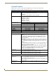
Many features are common to all products in the EXB family, as described in the following table.
Model -specific features are described in the following sections.
ICSLan Device Control Boxes - Common Features
Dimensions (HWD): • EXB-COM2, -I/O8, -IRS4 and -REL8:
1.00” x 4.35” x 5.15” (25.48 x 110.36 x 130.81)
•EXB-MP1:
1.00” x 3.04” x 4.82” (25.48cm x 77.14cm x 122.43cm)
Weight: • EXB-COM2: 1 lb (454 g)
• EXB-I/O8: 1 lb (454 g)
• EXB-IRS4: 1 lb (454 g)
• EXB-MP1: 1 lb (454 g)
• EXB-REL8: 1 lb (454 g)
Power Requirements: PoE (Power-over-Ethernet).
Idle (minimum) Power Draw: Busy (maximum) Power Draw
• EXB-COM2: 40mA 1.92 watts 40mA 1.92 watts
• EXB-IO8: 30mA 1.44 watts 40mA 1.92 watts
• EXB-IRS4: 40mA 1.92 watts 50mA 2.4 watts
• EXB-MP1 40mA 1.92 watts 40mA 1.92 watts
• EXB-REL8: 40mA 1.92 watts 70mA 3.36 watts
Enclosure: Metal with black matte finish
Front Panel Components
ID Pushbutton: The ID Pushbutton serves four functions:
• ID Mode: Used in conjunction with the ID Mode feature in NetLinx Studio, a
momentary push assigns a device address to the Module. See the Using
"Identify Mode" to Set the Device Address on the EXB Modules section on
page 13 for details.
• Static/DHCP: If the button is pressed and held for 10 seconds or longer and
then released, the unit toggles between static and dynamic IP addressing. See
the Toggling Between Static and DHCP IP Addressing section on page 14 for
details.
• Factory Reset: If the ID button is held for 10 seconds or longer during the boot
process, the unit will reset to factory defaults. See the Performing a Factory
Reset section on page 14 for details.
• Factory Image: If the ID pushbutton is held for 20 seconds and released while
the Module is booting up, the Module will restore itself to a factory firmware
image. See the Resetting the Unit to the Factory Default Firmware
Image section on page 14 for details.
Status LED: The green Status LED indicates unit status.
See the Detailed LED Behavior section on page 4 for details.
L/A LED: The green L/A (Link / Active) LED indicates communication status.
See the Detailed LED Behavior section on page 4 for details.
Rear Panel Components
Ethernet / PoE
Connector
RJ-45 connector provides IP communication and PoE.
This is an Auto MDI/MDI-X enabled port, therefore either straight-through or
crossover Ethernet cables can be used.
Note: The Ethernet connector is located on the front panel of the EXB-MP1 (see
FIG. 9 on page 31)
Module Specific
Connectors
Varies per model - refer to Connections and Wiring in each of the following
sections.