
Instruction manual

For warranty information, see www.amx.com.
08/2013
©2013 AMX. All rights reserved. AMX and the AMX logo are registered trademarks of AMX.
AMX reserves the right to alter specifications without notice at any time.
3000 RESEARCH DRIVE, RICHARDSON, TX 75082 • 800.222.0193 • fax 469.624.7153 • technical support 800.932.6993 • www.amx.com
93-1010-320 REV: G
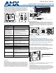
Twisted Pair Cable Pinouts and RJ-45 LEDs
The DXLink port (RJ-45 connector) on the rear of the Transmitters uses twisted pair
cable. FIG. 5 shows two pinouts that can be used. FIG. 6 shows LEDs for the port.
Before installing the Transmitter:
Wallplate TX – remove mounting bracket.
If a network connection is required, set #3 Toggle to ON.
If the gang box is not already installed, install it now (see previous page).
To install the Wallplate TX:
1. Attach the Wallplate TX mounting bracket to the gang box.
2. Attach a twisted pair cable from the DXLink Input Board on the switcher through
the mounting bracket to the DXLink connector on rear of Wallplate TX (FIG. 7).
3. Reattach the unit to the mounting bracket.
To install the Decor Wallplate TX:
1. Attach a twisted pair cable from the DXLink Input Board on the switcher to the
DXLink connector on the rear of the Decor Wallplate TX.
2. Attach unit to back box with four screws through the large screw holes.
3. Check LEDs for normal display (see table in right-hand column).
4. Attach customer provided decor style front cover plate to the unit.
Important: Do not
use the RJ-45 connector on rear of the Transmitter to connect to a
standard Ethernet Network. Use this connector for signal transport only.
Attaching Signal and Control Cables
Important: Transmitters must be securely mounted and connected to the switcher
before attaching the remaining cables.
To attach cables to the Transmitter:
1. HDMI input – Attach an HDMI cable from the source to HDMI In connector.
2. Analog video input – Attach HD-15 cable from source to analog video connector.
3. Stereo jack (optional) – Insert analog audio cable from source into Stereo jack.
4. USB Host (optional) – Attach USB cable from PC to USB (mini-B) port.
5. If necessary, set the video and audio formats using SEND_COMMANDs (see
the Instruction Manual).
6. Check LEDs for normal display (see table in right-hand column).
Note: Use DVI cable via an adapter (advanced HDMI audio support not available).
USB Host Port Provides HID Support
The USB Host (mini-B) port on the front enables USB keyboard and mouse signals
from a DXLink RX to be sent to a connected PC.
Additional Buttons and Port
Reset Button
The Reset button resets the Transmitter’s CPU (see the Instruction Manual).
Program Port
This USB mini-B port supports DGX Configuration Software for programming a
custom EDID.
ID Button
The ID button can be used to toggle between static and DHCP IP addressing, assign
a device address, reset the factory defaults, and restore the factory firmware image
(see the Instruction Manual).
Powering the Wallplate TX and the Decor Wallplate TX
The switcher provides power for the TXs over twisted pair cable. Approved DXLink
power sourcing devices are listed in the Specifications table on the previous page.
Important: AMX does not
support the use of any other PoE injectors as these may
potentially damage the DXLink equipment.
This table shows LED states on initial power up. If not normal, check connections.
* The LEDs for Digital Video, Analog Video, and Audio each indicate the configured state of
the connectors, not necessarily the presence of signals through the Transmitter.
** When an analog video signal is being received from the source device, only one of the
three analog video LEDs will be green at any time.
Tip: If the Wallplate TX’s location makes the bottom edge difficult to see, slide a white
piece of paper or a small mirror under the edge to view LED status.
Signal Precedence
With cables attached to each input on the Transmitters (see FIG. 8), the default
precedence for signal transmission is for HDMI with embedded digital audio. To
transmit either analog video or analog audio without detaching the HDMI connector,
the Transmitter’s precedence settings must be changed using SEND_COMMANDs.
For information, see the Instruction Manual.
Troubleshooting
Try the following and check the Instruction Manual before calling technical support.
Check all power connections in the system.
Check the RJ-45 (DXLink) cable connection between the Transmitter and
the switcher.
Check the source and destination devices to ensure that they function correctly.
Additional Information Covered in Instruction Manual
For information on the following, see the Instruction Manual – DXLink Twisted Pair
Transmitters/Receiver at www.amx.com:
• Pinouts for VGA, component, S-Video, and composite
• NetLinx control and programming commands, Telnet commands
• IR file transfers, upgrading firmware image, restoring factory default settings
FIG. 5
RJ-45 connector pinouts
FIG. 6 DXLink port LEDs
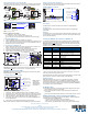
FIG. 7 Connect twisted pair cable to DXLink connector on rear of TX (Wallplate TX shown)
FIG. 8 Attach signal and control cables (Wallplate TX shown)
Yellow LED
Green LED
On - Authenticated HDCP
Off - No Video
Blinking - Video active; no HDCP
On - Connection is active
Off - Connection is not active
Decor Wallplate TX
Wallplate TX
DXLink output
Wallplate TX
Ground screw (see
on previous page)
Decor Wallplate TX
connector
“Technical Ground”
USB Host
HDMI Input and
Stereo Audio Input
HD-15 Input and
Analog Video LEDs
and Audio LED
Digital Video LED
Power LED
Note: Connector
arrangement
differs between
the Wallplate TX
and Decor TX.
FIG. 9 Wallplate TX (left) and Decor Wallplate TX (right)
LED Power Up -
Normal State
Indicates
Digital Video* Green Configured to pass HDMI with embedded audio
Analog Video* One
of the three LEDs
is Green**
Configured to pass analog video:
• C (composite) or Y/c (two component)
• Y/Pb/Pr or RGB (three component)
• RGBHV (five component) or RGBS (four component)
Audio* Green Configured to pass analog audio (coupled with digital or
analog video path)
Power Green Power is applied
Wallplate TX LEDs (on bottom edge) and Decor Wallplate TX LEDs (front center)
NetLinx - L, Link/Act
Green Active LAN connection to an AMX Network
(Blinking = #3 Toggle OFF)
NetLinx - S, Status Green Unit status
DXLink - Yellow, HDCP
Yellow
Flashing
Off
• Authenticated HDCP
• Video is active; no HDCP
•No Video
DXLink - Green Green DXLink connection is established
Wallplate TX - Bottom edge
NetLinx LEDs
DXLink LEDs
Program port
Reset button
ID button
Wallplate TX - Left edge
NetLinx LEDs
DXLink LEDs
Program port
Reset button
ID button
Decor Wallplate TX - Front