
Instruction manual

Installation and Setup
44
Instruction Manual – DXLink Fiber™ Transmitters and Receivers, Duplex
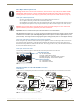
8. ICS LAN 10/100 connector (optional) – Attach a twisted pair cable from this connector to a LAN. Note that the
#1 Toggle on the DIP switch must be set to ON to enable this port.
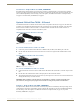
9. Local Out port (optional) – On the front of the unit, attach an HDMI cable from a local monitor to the Local Out
(HDMI) connector.
10. Program port (optional) – On the front of the unit, attach a USB mini-B cable from a PC to the Program port.
11. USB Host port (optional) – Attach USB cable from a PC to the Host USB-mini A/B port. The port’s default is
“enabled.” The USB LED on the front monitors this port. For USB support information, see page 23. For USB
SEND_COMMAND information, see page 82.
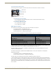
12. If necessary, set the video and audio formats using SEND_COMMANDs (for NetLinx programming information,
see page 66).
Note: When digital audio and/or analog stereo audio cables are plugged into the TX, the Audio LEDs on the
front of the units turn green to show that audio is present and is being incorporated into the HDMI line and is
also available on the DXLink Fiber RX at the Audio Out connector.
Note: The ID Pushbutton places the unit in ID Mode for setting the NetLinx ID (device only) and provides
additional functionality, such as placing the device in Static IP Mode or DHCP Mode. For complete
information, see page 57.
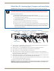
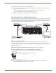
DXLink Fiber TX – Applying Power
To apply power to the DXLink Fiber TX:
1.
Plug the cord from the desktop power supply (provided) into the power jack on rear of the unit (2.1 mm DC jack for
12 V local power).
2. Plug the desktop power supply into an AC external power source.
The Power LED on the front of the unit turns a constant green, which indicates a ready state. Some LEDs turn a
constant color while some blink first. For normal LED display, see table below.
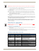
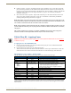
DXLink Fiber Transmitters, Duplex – Indicator LEDs
The LED indicators are listed in the table as they appear on the front of the unit from left to right.
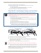
Caution: When you make the connection in Step 8, be careful not to create a network loop (see page 38).
Caution: The provided desktop power supply must be used to power the DXLink Fiber TX, and it must not
be altered in any way.
DXLink Fiber TX LEDs Normal Display Indicates
Power Green Power is applied to the unit
Digital Video Green A digital signal is present through the unit
Audio Green A digital audio signal is present through the unit
Analog Video One of the 3 LEDs
is Green
Type of analog video present through the unit:
• C (composite) or Y/C (2 component)
• Y/PB/PR or RGB (3 component)
• RGBHV (5 component) or RGBS (4 component)
IR TX Red IR TX active communication
IR RX Yellow IR RX active communication
232 (Serial) TX Red Serial TX active communication
232 (Serial) RX Yellow Serial RX active communication
NetLinx Link/Act Green Active LAN connection to an AMX Network
NetLinx Status Green LAN connection is active
CEC OFF CEC is not currently supported
USB Yellow USB port connection is established