
Instruction manual


Installation and Setup
38
Instruction Manual – DXLink Fiber™ Transmitters and Receivers, Duplex
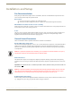
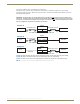
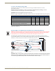
Avoiding Network (Ethernet) Loops
Only one connection to a LAN is permitted within a switching system with DXLink Fiber support. Network loops must
be avoided (see FIG. 11).
Example
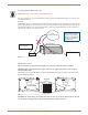
In the example in FIG. 11, a network loop was created when the Enova DGX 16 was connected to a LAN and one of its
DXLink Fiber Transmitters was connected to the same LAN. The Transmitter must be disconnected from the LAN. The
same problem would also occur if an enclosure and one (or more) of its DXLink Fiber Receivers were connected to a
common LAN. Remember to avoid network loops.
DIP Switch Location
Tip: For easiest access to the DIP switch toggles, we recommend setting them before installation.
Important: When setting the DIP switch toggles, make sure any toggles that need to be ON are flipped
toward the AMX sticker.
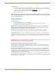
DIP switch toggles for enabling/disabling special Receiver/Transmitter functionality are located on the bottom of the
Receiver and the Transmitters.
Important: DIP switch settings on all DXLink Fiber units are read only on reboot. After the settings are read,
any adjustment of the toggles will not be implemented and will not affect the system.
Caution: Be careful not to create a network (Ethernet) loop.
LAN
Local Area Network
Destination device
Source device
Transmitter
LAN
connection
Enova DGX 16
Note: A network loop is
created when an enclosure
and one or more DXLink
Fiber TXs or RXs within the
system are connected to
a common LAN.
FIG. 11 Avoid network loops
FIG. 12 DIP switch on bottom of Transmitters and Receivers
ReceiverTransmitter
DIP switch