
Specifications


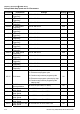


Chapter 5 Parameters|VFD-B Series
Revision July 2008, BE16, SW V4.08 & V5.00 5-7
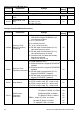
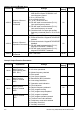
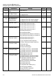
Parameter Explanation Settings
Factory
Setting
Customer
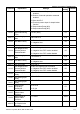
18: Auxiliary motor No.3
19: Heat sink overheat warning
20: AC motor drive ready
21: Emergency stop indication
22: Desired frequency attained 2
23: Software brake signal
24: Zero speed output signal
25: Under-current detection
26: Operation indication (H>=Fmin)
27: Feedback signal error
28: User-defined low-voltage detection
29: Brake control (Desired frequency attained
3)
03-04 Desired Frequency
Attained 1
0.00 to 400.00 Hz 0.00
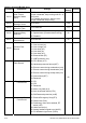
00: Analog frequency meter
01: Analog current meter
02: Output voltage
03: Output frequency command
04: Output motor speed
03-05
Analog Output
Signal
05: Load power factor (cos90
o
to Cos0
o
)
00
03-06 Analog Output Gain 01 to 200% 100
03-07 Digital Output
Multiplying Factor
01 to 20 01
03-08 Terminal Count
Value
00 to 65500 00
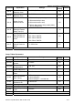
03-09
Preliminary Count
Value
00 to 65500 00
03-10
Desired Frequency
Attained 2
0.00 to 400.00 Hz 0.00
00: Preliminary count value attained, no EF
display
03-11
EF Active When
Preliminary Count
Value Attained
01: Preliminary count value attained, EF
active
00
00: Fan always ON
01: 1 minute after AC motor drive stops, fan
will be OFF
02: AC motor drive runs and fan ON, AC
motor drive stops and fan OFF
03-12 Fan Control
03: Fan ON to run when preliminary heatsink
temperature attained
00
03-13
Brake Release
Frequency
0.00 to 400.00Hz 0.00
03-14
Brake Engage
Frequency
0.00 to 400.00Hz 0.00