
Specifications


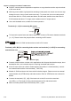


Chapter 2 Installation and Wiring|VFD-B Series
Revision July 2008, BE16, SW V4.08 & V5.00 2-23
Terminal
Symbol
Terminal Function
Factory Settings (SINK)
ON: Connect to DCM
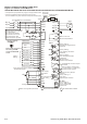
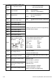
MO1
Multi-function Output 1
(Photocoupler)
MO2
Multi-function Output 2
(Photocoupler)
MO3
Multi-function Output 3
(Photocoupler)
Maximum 48VDC, 50mA
Refer to Pr.03-01 to Pr.03-03 for programming
MO1~MO3-DCM
MO1~MO3
MCM
Internal Circuit
Max: 48Vdc
50mA
MCM Multi-function output common Common for Multi-function Outputs
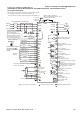
+10V Potentiometer power supply +10VDC 20mA
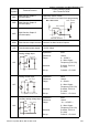
AVI
Analog voltage Input
ACM
AVI
+10V
internal circuit
AVI circuit
Impedance: 47kΩ
Resolution: 10 bits
Range: 0 ~ 10VDC =
0 ~ Max. Output
Frequency (Pr.01-00)
Selection: Pr.02-00, Pr.02-13,
Pr.10-00
Set-up: Pr.04-00 ~ Pr.04-03
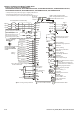
ACI
Analog current Input
ACM
ACI
internal circuit
ACI circuit
Impedance: 250Ω
Resolution: 10 bits
Range: 4 ~ 20mA =
0 ~ Max. Output
Frequency (Pr.01-00)
Selection: Pr.02-00, Pr.02-13,
Pr.10-00
Set-up: Pr.04-11 ~ Pr.04-14
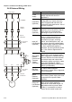
AUI
Auxiliary analog voltage input
ACM
AUI
+10
~
-10V
internal circuit
AUI circuit
Impedance: 47kΩ
Resolution: 10 bits
Range: -10 ~ +10VDC =
0 ~ Max. Output
Frequency (Pr.01-00)
Selection: Pr.02-00, Pr.02-13,
Pr.10-00
Set-up: Pr.04-15 ~ Pr.04-18