
Specifications


Chapter 2 Installation and Wiring|VFD-B Series
Revision July 2008, BE16, SW V4.08 & V5.00 2-15
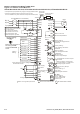
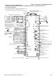
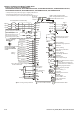
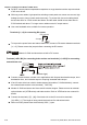
Figure 2 for models of VFD-B Series
VFD022B21A, VFD037B23A/43A/53A, VFD055B23A/43A/53A, VFD075B23A/43A/53A,
VFD110B23A/43A/53A
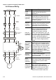
Br ak e r es isto r (o pt ion al )
Refer to Appendix B for the use of
special brake resi stor
+1
+2/B1
B2
Jumper
* For the single phase drives, the AC input line can
be connected to any two of the three input terminals R,S,T
* Three phase input power may apply to single phase drives.
-(minus sign)
BR
DC chock
(optional)
AVI
ACI
AUI
ACM
4~20mA
-10~+10V
+10V
5K
3
2
1
Power supply
+10V 20mA
Master Frequency
0 to 10 V 47K
Analog Signal Common
E
FWD
REV
JOG
EF
MI1
MI2
MI3
MI4
MI6
TRG
MI5
DCM
+24V
Sw1
Sink
Source
Fact ory Settin g:
SINK Mode
FWD/STOP
REV/STOP
JOG
E.F.
Multi-step 1
Multi-step 2
Multi-step 3
Multi-step 4
RESET
Accel/Decel prohibit
Counter
Digital Signal Common
Factory
setting
* Don't apply the mains voltage directly
to above terminals.
E
Please refer to Figure 4
for wiring of S INK
mode and SOURCE
mode.
R(L1)
S(L2)
T(L3)
Fuse/NFB(None Fuse Breaker)
SA
OFF
ON
MC
MC
RB
RC
R(L1)
S(L2)
T(L3)
E
Analog Multi-function Output
Terminal
Factory default: Analog freq.
/ current meter
0~10VDC/2mA
MO3
U(T1)
V(T2)
W(T3)
IM
3~
MO1
MO2
AFM
ACM
RA
RB
RC
MCM
RS-485
Motor
Factory setting:
indicates during operation
48V50mA
Factory setting:
Freq. Setting Indication
Factory setting:
Low-voltage Indication
Multi-function
Photocoulper Output
Analog Signal common
Seri al interface
1: EV 2: GND
5:Reserved
6: Reserved
3: SG-
4: SG+
DFM
DCM
Digital Frequency Output
Terminal
Factory setting: 1:1
Duty=50%
Digital Signal Common
48V50mA
48V50mA
E
E
Please refer to Control
Terminal Explanation.
6 1
Main circuit (power) terminals
Control circuit terminals
Shielded leads & Cable
Recommended Circuit when
power supply is turned OFF
by a fault output.
The contact will be ON
when the fault occurs to
turn off the power and
protect the power system.