
Specifications


Appendix B Accessories|VFD-B Series
Revision July 2008, BE16, SW V4.08 & V5.00 B-23
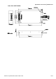
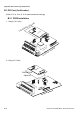
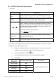
B.3.1.2 PG-02 Terminal Descriptions
1. Terminals
Terminal Symbols Descriptions
VP
Power source of PG-02 (FSW1 can be switched to 12V or 5V)
Output Voltage: (+12VDC ±5% 200mA) or (+5VDC ±2% 400mA)
DCM
Power source (VP) and input signal (A, B) common
A-
A
,B-
B
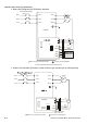
Input signal from Pulse Generator. Input type is selected by FSW2. It
can be 1-phase or 2-phase input. Maximum 500kP/sec (z-phase
function is reserved). If the voltage exceeds 12V, it needs to use TP
type with connecting the external current limiting resistor(R). The
current should be within 5 to 15mA.
The formal of current limiting resistor is:
mA
R
VVin
mA 15
480
2
5 ≤
+Ω
−
≤
A/O, B/O
PG-02 output signal for use with RPM Meter. (Open Collector)
Maximum DC24V 100mA
COM
PG-02 output signal (A/O, B/O) common.
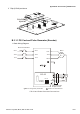
2. Wiring Notes
The control, power supply and motor leads must be laid separately. They must not be fed
through the same cable conduit / trunk.
a. Please use a shielded cable to prevent interference. Do not run control wires
parallel to any high voltage AC power line (220 V and above).
b. Connect shielded wire to DCM
only.
c. Recommended wire size 0.21 to 0.81mm
2
(AWG24 to AWG18).
d. Wire length:
Types of Pulse
Generators
Maximum Wire Length Wire Gauge
Output Voltage 50m
Open Collector 50m
Line Driver 300m
Complementary 70m
1.25mm
2
(AWG16) or above