
Specifications


Chapter 5 Parameters|VFD-B Series
Revision July 2008, BE16, SW V4.08 & V5.00 5-99
The base is Pr.01-00. When in PID feedback control, if | Source of PID reference target -
feedback | > Pr.10-16 and exceeds Pr.10-08 detection time, the AC drive will operate
according to Pr.10-09.
10 - 10 PG Pulse Range Unit: 1
Settings 1 ~ 40000 (Max=20000 for 2-pole motor) Factory Setting: 600
A Pulse Generator (PG) or encoder is used as a sensor that provides a feedback signal of the
motor speed. This parameter defines the number of pulses for each cycle of the PG control.
For PG or encoder feedback an option PG-card is needed.
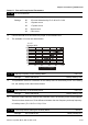
10 - 11 PG Input
Factory Setting: 00
Settings 00 Disable PG
01 Single phase
02 Forward / Counterclockwise rotation
03 Reverse / Clockwise rotation
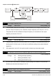
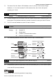
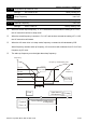
The relationship between the motor rotation and PG input is illustrated below:
FWD
CCW
REV
CW
PULSE
GENERATOR
PG
10-11=02
10-11=03
A phase leads B phase
A phase
A phase
A phase
B phase
B phase
B phase
CW
B phase leads A phase
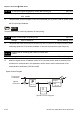
10 - 12 ASR (Auto Speed Regulation) control (with PG only) (P) Unit: 0.1
Settings 0.0 to 10.0 Factory Setting: 1.0
This parameter specifies Proportional control and associated gain (P), and is used for speed
control with PG (encoder) feedback.
NOTE
The parameter can be set during operation for easy tuning.