
Specifications


Chapter 5 Parameters|VFD-B Series
5-96 Revision July 2008, BE16, SW V4.08 & V5.00
Group 10: PID Control
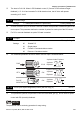
10 - 00 Input Terminal for PID Feedback
Factory Setting: 00
Settings 00 Inhibit PID operation: external terminals AVI, ACI may be used for
frequency command if required (Pr.02-00).
01 Negative PID feedback from external terminal AVI (0 ~ +10VDC).
02 Negative PID feedback from external terminal ACI (4 ~ 20mA).
03 Positive PID feedback from external terminal AVI (0 ~ +10VDC).
04 Positive PID feedback from external terminal ACI (4 ~ 20mA).
Note that the measured variable (feedback) controls the output frequency (Hz). Select input
terminal accordingly. Make sure this parameter setting does not conflict with the setting for
Pr.02-00 (Master Frequency).
When Pr.02-00 is set to 01 or 02, the set point (Master Frequency) for PID control is obtained
from the AVI/ACI external terminal (0 to +10V or 4-20mA) or from multi-step speed. When
Pr.02-00 is set to 00, the set point is obtained from the keypad.
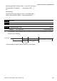
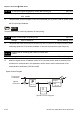
Negative feedback means: +target value - feedback
Positive feedback means: -target value + feedback.
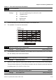
10 - 01 Gain Over the PID Detection Value Unit: 0.01
Settings 0.00 to 10.00 Factory Setting: 1.00
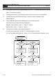
This is the gain adjustment over the feedback detection value. Refer to PID control block
diagram in Pr.10-06 for detail.
10 - 02 Proportional Gain (P) Unit: 0.01
Settings 0.0 to 10.0 Factory Setting: 1.0
This parameter specifies proportional control and associated gain (P). If the other two gains (I
and D) are set to zero, proportional control is the only one effective. With 10% deviation (error)
and P=1, the output will be P x10% x Master Frequency.
NOTE
The parameter can be set during operation for easy tuning.