
Specifications


Chapter 5 Parameters|VFD-B Series
5-92 Revision July 2008, BE16, SW V4.08 & V5.00
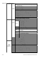
Content Address Function
12: Current exceeds 2 times rated current during steady state
operation (ocn)
13: Ground Fault (GFF)
14: Low voltage (Lv)
2100H 15: CPU failure 1 (cF1)
16: CPU failure 2 (cF2)
17: Base Block
18: Overload (oL2)
19: Auto accel/decel failure (cFA)
20: Software protection enabled (codE)
21: EF1 Emergency stop
22: PHL (Phase-Loss)
23: cEF (Preliminary count value attained, EF active)
24: Lc (Under-current)
25: AnLEr (Analog feedback signal error)
26: PGErr (PG feedback signal error)
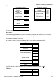
Status of AC drive
LED: 0: light off, 1: light up
00: RUN LED
01: STOP LED
02: JOG LED
03: FWD LED
2101H
Bit 0-4
04: REV LED
Bit 5 0: F light off, 1: F light on
Bit 6 0: H light off, 1: H light on
Bit 7 0: “u” light off, 1: “u” light on
Bit 8
1: Master frequency Controlled by communication
interface
Bit 9 1: Master frequency controlled by analog signal
Bit 10
1: Operation command controlled by
communication interface
Bit 11 1: Parameters have been locked
Bit 12 0: AC drive stops, 1: AC drive operates
Bit 13 1: Jog command
Bit 14-15 Reserved
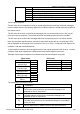
2102H Frequency command (F)
2103H Output frequency (H)
2104H Output current (AXXX.X)
2105H DC-BUS Voltage (UXXX.X)
2106H Output voltage (EXXX.X)
2107H Step number of Multi-Step Speed Operation
2108H Step number of PLC operation
2109H Content of external TRIGGER
210AH Power factor angle
Status
monitor
Read only
210BH Estimated torque ratio (XXX.X)
210CH Motor speed (rpm)
210DH PG pulse (low word) /unit time (Pr.10-15)
210EH PG pulse (high word) /unit time (Pr.10-15)
210FH Output power (KW)
2110H Reserved
2200H Feedback Signal (XXX.XX %)