
Specifications


Chapter 5 Parameters|VFD-B Series
5-52 Revision July 2008, BE16, SW V4.08 & V5.00
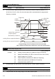
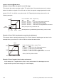
Example 8: Use negative slope
In this example, the use of negative slope is shown. Negative slopes are used in applications for
control of pressure, temperature or flow. The sensor that is connected to the input generates a
large signal (10V or 20mA) at high pressure or flow. With negative slope settings, the AC motor
drive will slow stop the motor. With these settings the AC motor drive will always run in only one
direction (reverse). This can only be changed by exchanging 2 wires to the motor.
60Hz
0Hz
0V
4m
A
10V
20mA
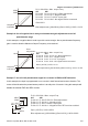
Pr.01-00=60Hz--Max. output Freq.
AVI ACI AUI
Pr.04-00 Pr.04-11 Pr.04-15=100%--Bias adjustment
Pr.04-01 Pr.04-12 Pr.04-16=0--Positive bias
Pr.04-02 Pr.04-13 Pr.04-17=100%--Input gain
Pr.04-03 Pr.04-14 Pr.04-18=1--Negative bias: REV motion enabled
Gain:(10V/10V)*100%=100%
Bias adjustment:((60Hz/60Hz)/(Gain/100%))*100%=100%
negative slope
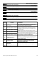
04 - 19
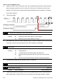
AVI Analog Input Delay
Unit: 0.01
Settings 0.00 to 10.00 sec Factory Setting: 0.05
04 - 20 ACI Analog Input Delay Unit: 0.01
Settings 0.00 to 10.00 sec Factory Setting: 0.05
04 - 21 AUI Analog Input Delay Unit: 0.01
Settings 0.00 to 10.00 sec Factory Setting: 0.05
These input delays can be used to filter noisy analog signals.
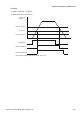
04 - 22 Analog Input Frequency Resolution
Factory Setting: 01
Settings 00 0.01Hz
01 0.1Hz
It is used to set the unit of the resolution of frequency command when the input source is an
analog signal.