Preface Thank you for choosing DELTA’s high-performance VFD-B Series. The VFD-B Series is manufactured with high-quality components and materials and incorporates the latest microprocessor technology available. This manual is to be used for the installation, parameter setting, troubleshooting, and daily maintenance of the AC motor drive. To guarantee safe operation of the equipment, read the following safety guidelines before connecting power to the AC motor drive.
WARNING! 1. DO NOT use Hi-pot test for internal components. The semi-conductor used in the AC motor drive is easily damaged by high-pressure. 2. There are highly sensitive MOS components on the printed circuit boards. These components are especially sensitive to static electricity. To prevent damage to these components, do not touch these components or the circuit boards with metal objects or your bare hands. 3. Only qualified persons are allowed to install, wire and maintain AC motor drives.
Table of Contents Preface ............................................................................................................. i Table of Contents .......................................................................................... iii Chapter 1 Introduction ................................................................................ 1-1 1.1 Receiving and Inspection ................................................................... 1-1 1.1.1 Nameplate Information........................
2.4.2 External Wiring .......................................................................... 2-18 2.4.3 Main Terminals Connections ..................................................... 2-19 2.4.4 Control Terminals ...................................................................... 2-21 2.4.5 Main Circuit Terminals............................................................... 2-26 Chapter 3 Start Up .......................................................................................3-1 3.
7.7 Display of PU01 is Abnormal.............................................................. 7-5 7.8 Phase Loss (PHL) .............................................................................. 7-5 7.9 Motor cannot Run............................................................................... 7-6 7.10 Motor Speed cannot be Changed..................................................... 7-7 7.11 Motor Stalls during Acceleration....................................................... 7-8 7.
B.3.2.2 PG Card and Pulse Generator (Encoder)..........................B-26 B.3.2.3 PG-03 Terminal Descriptions ............................................B-27 B.4 Remote Controller RC-01 ................................................................ B-30 B.5 Remote Panel Adapter (RPA 01) .................................................... B-31 B.6 AC Reactor...................................................................................... B-32 B.6.1 AC Input Reactor Recommended Value ..............
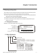
Chapter 1 Introduction 1.1 Receiving and Inspection This VFD-B AC motor drive has gone through rigorous quality control tests at the factory before shipment. After receiving the AC motor drive, please check for the following: Check to make sure that the package includes an AC motor drive, the User Manual/Quick Start and CD, dust covers and rubber bushings. Inspect the unit to assure it was not damaged during shipment.
Chapter 1 Introduction|VFD-B Series 1.1.3 Series Number Explanation 007B23A 0T 7 01 Production number Production week 230V 3-phase 1HP(0.75kW) Production year 2007 Production factory (Taoyuan) Model If the nameplate information does not correspond to your purchase order or if there are any problems, please contact your distributor. 1.1.4 Drive Frames Frame Power range Models A 1hp (0.75kW) VFD007B23A/43A/53A A1 1-2hp (0.75-1.5kW) VFD007B21A, VFD015B21A/23A/43A/53A A2 2-3hp (1.5-2.
Chapter 1 Introduction|VFD-B Series 7.5-15HP/5.5-11kW (Frame C) Revision July 2008, BE16, SW V4.08 & V5.
Chapter 1 Introduction|VFD-B Series 40-100HP/30-75kW (Frame E, E1) 75-100HP/55-75kW (Frame F) 1.3 Preparation for Installation and Wiring 1.3.1 Remove Keypad 1-3HP/0.75-2.2kW (Frame A, A1, A2) 1-4 3-5HP/2.2-3.7kW (Frame B) Revision July 2008, BE16, SW V4.08 & V5.
Chapter 1 Introduction|VFD-B Series 7.5-15HP/5.5-11kW (Frame C) 20-30HP/15-22kW (Frame D) 40-100HP/30-75kW (Frame E, E1) 75-100HP/55-75kW (Frame F) Revision July 2008, BE16, SW V4.08 & V5.
Chapter 1 Introduction|VFD-B Series 1.3.2 Remove Front Cover 1-6 1-3HP/0.75-2.2kW (Frame A, A1, A2) 3-5HP/2.2-3.7kW (Frame B) 7.5-15HP/5.5-11kW (Frame C) 20-30HP/15-22kW (Frame D) Revision July 2008, BE16, SW V4.08 & V5.
Chapter 1 Introduction|VFD-B Series 40-100HP/30-75kW (Frame E, E1) 75-100HP/55-75kW (Frame F) 1.4 Lifting Please carry only fully assembled AC motor drives as shown in the following. For 40-100HP (Frame E, E1 and F) Step 1 Revision July 2008, BE16, SW V4.08 & V5.
Chapter 1 Introduction|VFD-B Series Step 3 Step 4 1.5 Storage The AC motor drive should be kept in the shipping carton or crate before installation. In order to retain the warranty coverage, the AC motor drive should be stored properly when it is not to be used for an extended period of time. Storage conditions are: Store in a clean and dry location free from direct sunlight or corrosive fumes. Store within an ambient temperature range of -20 °C to +60 °C.
Chapter 2 Installation and Wiring 2.1 Ambient Conditions Install the AC motor drive in an environment with the following conditions: Operation Air Temperature: Relative Humidity: Atmosphere pressure: Installation Site Altitude: Vibration: -10 ~ +40°C (14 ~ 104°F) <90%, no condensation allowed 86 ~ 106 kPa <1000m <20Hz: 9.80 m/s2 (1G) max 20 ~ 50Hz: 5.88 m/s2 (0.
Chapter 2 Installation and Wiring|VFD-B Series 5. When installing multiple AC motor drives in the same cabinet, they should be adjacent in a row with enough space in-between. When installing one AC motor drive below another one, use a metal separation barrier between the AC motor drives to prevent mutual heating. 6. Prevent fiber particles, scraps of paper, saw dust, metal particles, etc. from adhering to the heatsink. Minimum Mounting Clearances H Air Flow FWD REV PROG DATA W W H HP 1-5HP 7.
Chapter 2 Installation and Wiring|VFD-B Series 2.3 Dimensions (Dimensions are in millimeter and [inch]) Frame A: VFD007B23A/43A/53A 145.0 [5.71] 118.0 [4.65] 108.0 [4.25] 185.0 [7.28] 173.0 [6.81] 5.5[0.22] 0.87] 22.0[ 10](2X) 28.0[ 1. . 75[0 11] 8.7 [0.34] R2 . 5.5[0.22] Revision July 2008, BE16, SW V4.08 & V5.
Chapter 2 Installation and Wiring|VFD-B Series Frame A1: VFD007B21A, VFD015B21A/23A/43A/53A 160.0 [6.30] 118.0 [4.65] 108.0 [4.25] 185.0 [7.28] 173.0 [6.81] 5.5[0.22] 0.87] 22.0[ 10](2X) 28.0[ 1. 8.7 [0.34] 1] 5[0.1 R2.7 5.5[0.22] 2-4 Revision July 2008, BE16, SW V4.08 & V5.
Chapter 2 Installation and Wiring|VFD-B Series Frame A2: VFD015B21B/23B, VFD022B23B/43B/53A 145.0 [5.71] 118.0 [4.65] 108.0 [4.25] 185.0 [7.28] 173.0 [6.81] 5.5[0.22] 22.0[ 0.87] 10](2X 28.0[ 1. ) 8.7 [0.34] .11] 75[0 R2. 5.5[0.22] Revision July 2008, BE16, SW V4.08 & V5.
Chapter 2 Installation and Wiring|VFD-B Series Frame B: VFD022B21A, VFD037B23A/43A/53A 150.0 [5.91] 135.0 [5.32] [ 0. 26 ] 160.2 [6.31] 244.3 [9.63] 260.0[10.24] 5 6. 28 X) (2 .0[ 1.1 3] 0.1 5[R 2 . R3 0]( 2X ) 11.3 [0.44] [ .0 22 ] 87 0. 6.5[0.26] UNIT : mm(inch) 2-6 Revision July 2008, BE16, SW V4.08 & V5.
Chapter 2 Installation and Wiring|VFD-B Series Frame C: VFD055B23A/43A/53A, VFD075B23A/43A/53A, VFD110B23A/43A/53A ] 28 0. 183.2 [7.22] R3 .5 [R 0. 14 ] 13.5 [0.53] 323.0 [12.72] 0[ 7. 303.0 [11.93] 200.0 [7.88] 185.6 [7.31] 7.0 [0.28] Revision July 2008, BE16, SW V4.08 & V5.
Chapter 2 Installation and Wiring|VFD-B Series Frame D: VFD150B23A/43A/53A, VFD185B23A/43A/53A, VFD220B23A/43A/53A 250.0 [9.84] 10.0 [ 0.39] 4 [ 2.0 1 .6 2-8 205.4 [8.08] 403.8 [15.90] 5 ]( 2 X) R 5. 13.0 [0.51] 28 .0 [ 1.1 0] 384.0 [15.12] 226.0 [8.90] 0. 2 0[R 0] 10.0 [0.39] Revision July 2008, BE16, SW V4.08 & V5.
Chapter 2 Installation and Wiring|VFD-B Series Frame E: VFD300B43A/53A, VFD370B43A/53A, VFD450B43A/53A 370.0 [14.57] 260.0 [10.24] 589.0 [23.19] 560.0 [22.05] 335.0 [13.19] 18.0 [0.71] 21.0[0.83] 132.5 [5.22] R6.5[0.25] 13.0[0.51] Revision July 2008, BE16, SW V4.08 & V5.
Chapter 2 Installation and Wiring|VFD-B Series Frame E1: VFD300B23A, VFD370B23A, VFD550B43C/53A, VFD750B43C/53A 370.0 [14.57] 260.0 [10.24] 589.0 [23.19] 560.0 [22.05] 595.0 [23.43] 335.0 [13.19] 18.0 [0.71] 21.0[0.83] 132.5 [5.22] R6.5[0.25] 13.0[0.51] 2-10 Revision July 2008, BE16, SW V4.08 & V5.
Chapter 2 Installation and Wiring|VFD-B Series Revision July 2008, BE16, SW V4.08 & V5.
Chapter 2 Installation and Wiring|VFD-B Series VFD-PU01 F H U VFD-PU01 RUN STOP JOG JOG FWD REV MODE PROG DATA RUN STOP RESET 2.4 Wiring After removing the front cover, check if the power and control terminals are clear of debris. Be sure to observe the following precautions when wiring. General Wiring Information Applicable Codes All VFD-B series are Underwriters Laboratories, Inc.
Chapter 2 Installation and Wiring|VFD-B Series 2.4.1 Basic Wiring Make sure that power is only applied to the R/L1, S/L2, T/L3 terminals. Failure to comply may result in damage to the equipment. The voltage and current should lie within the range as indicated on the nameplate. Check the following items after completing the wiring: 1. Are all connections correct? 2. No loose wires? 3.
Chapter 2 Installation and Wiring|VFD-B Series Figure 1 for models of VFD-B Series VFD007B21A/23A/43A/53A, VFD015B21A/21B/23A/23B/43A/53A, VFD022B23B/43B/53A * T hree phase input power may apply to single phase drives .
Chapter 2 Installation and Wiring|VFD-B Series Figure 2 for models of VFD-B Series VFD022B21A, VFD037B23A/43A/53A, VFD055B23A/43A/53A, VFD075B23A/43A/53A, VFD110B23A/43A/53A * T hree phase input power may apply to single phas e driv es.
Chapter 2 Installation and Wiring|VFD-B Series Figure 3 for models of VFD-B Series VFD150B23A/43A/53A, VFD185B23A/43A/53A, VFD220B23A/43A/53A, VF D300B23A/43A/53A, VFD370B23A/43A/53A, VFD450B43A/53A, VFD550B43C/53A, VFD750B43C/53A * T hree phase input power may apply to single phas e driv es.
Chapter 2 Installation and Wiring|VFD-B Series Figure 4 Wiring for SINK mode and SOURCE mode SINK Mode Sink SW1 Source FWD/STOP REV/STOP JOG E.F. +24V FWD REV JOG EF Multi-step1 MI1 Multi-step2 MI2 Multi-step3 Factory setting MI3 Multi-step4 MI4 RESET MI5 Accel./Decel. prohibit Counter Digital Signal Common *Don't apply the mains voltage directly to above terminals. SOURCE Mode Sink Sw1 Source FWD/STOP REV/STOP JOG E.F.
Chapter 2 Installation and Wiring|VFD-B Series 2.4.2 External Wiring Items Power Suppl y Power supply Fuse/NFB (Optional) There may be an inrush current during power up. Please check the chart of Appendix B and select the correct fuse with rated current. Use of an NFB is optional. Magnetic contactor (Optional) Please do not use a Magnetic contactor as the I/O switch of the AC motor drive, as it will reduce the operating life cycle of the AC drive.
Chapter 2 Installation and Wiring|VFD-B Series 2.4.
Chapter 2 Installation and Wiring|VFD-B Series DO NOT connect phase-compensation capacitors or surge absorbers at the output terminals of AC motor drives. With long motor cables, high capacitive switching current peaks can cause over-current, high leakage current or lower current readout accuracy. To prevent this, the motor cable should be less than 20m for 3.7kW models and below. And the cable should be less than 50m for 5.5kW models and above. For longer motor cables use an AC output reactor.
Chapter 2 Installation and Wiring|VFD-B Series WARNING! 1. Short-circuiting [B2] or [-] to [+2/B1] can damage the AC motor drive. Grounding terminals ( ) Make sure that the leads are connected correctly and the AC drive is properly grounded. (Ground resistance should not exceed 0.1Ω.) Use ground leads that comply with local regulations and keep them as short as possible. Multiple VFD-B units can be installed in one location.
Chapter 2 Installation and Wiring|VFD-B Series Terminal Symbol JOG Jog command EF External fault TRG External counter input MI1 Multi-function Input 1 MI2 Multi-function Input 2 MI3 Multi-function Input 3 MI4 Multi-function Input 4 MI5 Multi-function Input 5 MI6 Multi-function Input 6 Digital Frequency Meter (Open Collector Output) DFM-DCM Max: 48V 50mA DFM 50% internal circuit +24V DCM Factory Settings (SINK) Terminal Function 100% DC Voltage Source Digital Signal Common RA Mul
Chapter 2 Installation and Wiring|VFD-B Series Terminal Symbol Factory Settings (SINK) Terminal Function MO1 Multi-function Output 1 (Photocoupler) MO2 Multi-function Output 2 (Photocoupler) ON: Connect to DCM Maximum 48VDC, 50mA Refer to Pr.03-01 to Pr.
Chapter 2 Installation and Wiring|VFD-B Series Terminal Symbol Factory Settings (SINK) Terminal Function ON: Connect to DCM Analog output meter 0 to 10V, 2mA ACM circuit Impedance: AFM AFM 0~10V potentiometer Max. 2mA internal circuit ACM ACM Analog control signal (common) 470Ω Output current 2mA max Resolution: 8 bits Range: 0 ~ 10VDC Function: Pr.03-05 Common for AVI, ACI, AUI, AFM Control signal wiring size: 18 AWG (0.75 mm2) with shielded wire.
Chapter 2 Installation and Wiring|VFD-B Series General Keep control wiring as far away as possible from the power wiring and in separate conduits to avoid interference. If necessary let them cross only at 90º angle. The AC motor drive control wiring should be properly installed and not touch any live power wiring or terminals. NOTE If a filter is required for reducing EMI (Electro Magnetic Interference), install it as close as possible to AC drive.
Chapter 2 Installation and Wiring|VFD-B Series 2.4.5 Main Circuit Terminals Frame A, A1, A2: VFD007B21A/23A/43A/53A, VFD015B21A/21B//23A/23B/43A/53A, VFD022B23B/43B/53A S T R /L1 /L2 /L3 +1 +2 /B1 B2 V U W /T1 / T2 /T3 Control Terminal Torque: 4Kgf-cm (3 in-lbf) Wire: 12-24 AWG (3.3-0.2 mm2) Power Terminal Torque: 18 kgf-cm (15.6 in-lbf) Wire Gauge: 10-18 AWG (5.3-0.8 mm2) stranded wire, 12-18 AWG (3.3-0.8 mm2) solid wire Wire Type: Copper only, 75°C 2-26 Revision July 2008, BE16, SW V4.08 & V5.
Chapter 2 Installation and Wiring|VFD-B Series Frame B: VFD022B21A, VFD037B23A/43A/53A +1 +2 B1 - B2 U/T1 V/T2 W/T3 Screw Torque : 18Kgf-cm Wire Gauge : 18~10AWG R/L1 S/L2 T/L3 Control Terminal Torque: 4Kgf-cm (3 in-lbf) Wire: 12-24 AWG (3.3-0.2mm2) Power Terminal Torque: 18 kgf-cm (15.6 in-lbf) Wire Gauge: 10-18 AWG (5.3-0.8mm2) Wire Type: Stranded copper only, 75°C Revision July 2008, BE16, SW V4.08 & V5.
Chapter 2 Installation and Wiring|VFD-B Series Frame C: VFD055B23A/43A/53A, VFD075B23A/43A/53A, VFD110B23A/43A/53A POWER IM 3 MOTOR Control Terminal Torque: 4Kgf-cm (3 in-lbf) Wire: 12-24 AWG (3.3-0.2mm2) Power Terminal Torque: 30Kgf-cm (26 in-lbf) Wire: 8-12 AWG (8.4-3.3mm2) Wire Type: Stranded Copper only, 75°C NOTE To connect 6 AWG (13.3 mm2) wires, use Recognized Ring Terminals 2-28 Revision July 2008, BE16, SW V4.08 & V5.
Chapter 2 Installation and Wiring|VFD-B Series Frame D: VFD150B23A/43A/53A, VFD185B23A/43A/53A, VFD220B23A/43A/53A R/L1 S/L2 T/L3 +1 POWER +2 DC (+) - DC ( - ) V/T2 W/T3 IM 3 MOTOR Control Terminal Torque: 4Kgf-cm (3 in-lbf) Wire: 12-24 AWG (3.3-0.2 mm2) Power Terminal Torque: 30Kgf-cm (26 in-lbf) Wire: 2-8 AWG (33.6-8.4 mm2) Wire Type: Stranded Copper only, 75°C NOTE To connect 6 AWG (13.3 mm2) wires, use Recognized Ring Terminals Revision July 2008, BE16, SW V4.08 & V5.
Chapter 2 Installation and Wiring|VFD-B Series Frame E1: VFD300B23A, VFD370B23A, VFD550B43C, VFD750B43C, VFD550B53A, VFD750B53A POWER ALARM CHARGE R/L1 S/L2 T/L3 POWER +1 +2 Screw Torque: 200kgf-cm (173in-lbf) U/T1 V/T2 W/T3 IM 3 MOTOR Control Terminal Torque: 4Kgf-cm (3 in-lbf) Wire: 12-24 AWG (3.3-0.2 mm2) Power Terminal Torque: 200kgf-cm (173 in-lbf) Wire Gauge: 1 - 3/0 AWG (42.4-85 mm2) Wire Type: Stranded copper only, 75°C 2-30 Revision July 2008, BE16, SW V4.08 & V5.
Chapter 2 Installation and Wiring|VFD-B Series Frame E: VFD300B43A, VFD370B43A, VFD450B43A, VFD300B53A, VFD370B53A, VFD450B53A POWER ALARM CHARGE R/L1 S/L2 T/L3 POWER +1 +2 - U/T1 V/T2 2/T3 IM 3 MOTOR Control Terminal Torque: 4Kgf-cm (3 in-lbf) Wire: 12-24 AWG (3.3-0.2 mm2) Power Terminal Torque: 58.7kgf-cm (50.9 in-lbf) max. Wire Gauge: 2-6AWG (33.6-13.3 mm2) Wire Type: Stranded copper only, 75°C Revision July 2008, BE16, SW V4.08 & V5.
Chapter 2 Installation and Wiring|VFD-B Series 2-32 Revision July 2008, BE16, SW V4.08 & V5.
Chapter 3 Start Up 3.1 Preparations before Start-up Carefully check the following items before proceeding. Make sure that the wiring is correct. In particular, check that the output terminals U, V, W. are NOT connected to power and that the drive is well grounded. Verify that there are no short-circuits between terminals and from terminals to ground or mains power. Check for loose terminals, connectors or screws.
Chapter 3 Start Up|VFD-B Series 3.2 Operation Method Refer to 4.2 How to operate the digital keypad VFD-PU01 and chapter 5 parameters for setting. Please choose a suitable method depending on application and operation rule. The operation is usually used as shown in the following table.
Chapter 3 Start Up|VFD-B Series NOTE 1. Stop running immediately if any fault occurs and refer to the troubleshooting guide for solving the problem. 2. Do NOT touch output terminals U, V, W when power is still applied to L1/R, L2/S, L3/T even when the AC motor drive has stopped. The DC-link capacitors may still be charged to hazardous voltage levels, even if the power has been turned off. 3. To avoid damage to components, do not touch them or the circuit boards with metal objects or your bare hands.
Chapter 3 Start Up|VFD-B Series This page intentionally left blank. 3-4 Revision July 2008, BE16, SW V4.08 & V5.
Chapter 4 Digital Keypad Operation 4.1 Description of the Digital Keypad VFD-PU01 LED Display Display frequency, current, voltage and error, etc. F H U VFD-PU01 Status Display Display of drive status JOG Jog operation selector Left key Moves cursor to the left UP and DOWN Key Sets the parameter number and changes the numerical data, such as Master Frequency.
Chapter 4 Digital Keypad Operation|VFD-B Series Display Message Descriptions Displays the AC motor drive reverse run status. The counter value (C). Displays the selected parameter. Displays the actual stored value of the selected parameter. External Fault. Display “End” for approximately 1 second if input has been accepted by key. After a parameter value has been set, the new pressing value is automatically stored in memory. To modify an entry, use the , and keys.
Chapter 4 Digital Keypad Operation|VFD-B Series 4.2 How to Operate the Digital Keypad VFD-PU01 Selection mode STA RT F F F H U F H H H U U U MODE MODE F H U MODE MODE MODE GO START NO TE : In the selection mode, press to set the parameters. To set parameters F H U F H U F H U parameter set successfully F H U F H U parameter set error MODE move to previous display NO TE : In the parameter setting mode, you can press MODE to return to the selection mode.
Chapter 4 Digital Keypad Operation|VFD-B Series This page intentionally left blank. 4-4 Revision July 2008, BE16, SW V4.08 & V5.
Chapter 5 Parameters The VFD-B parameters are divided into 12 groups by property for easy setting. In most applications, the user can finish all parameter settings before start-up without the need for readjustment during operation.
Chapter 5 Parameters|VFD-B Series 5.1 Summary of Parameter Settings : The parameter can be set during operation.
Chapter 5 Parameters|VFD-B Series Parameter 00-10 Explanation Settings Factory Customer Setting Reserved Group 1 Basic Parameters Parameter 01-00 01-01 01-02 01-03 01-04 01-05 01-06 01-07 01-08 01-09 01-10 01-11 01-12 01-13 01-14 01-15 01-16 01-17 01-18 01-19 01-20 Explanation Maximum Output Frequency (Fmax) Maximum Voltage Frequency (Fbase) Maximum Output Voltage (Vmax) Settings Factory Customer Setting 50.00 to 400.00 Hz 60.00 0.10 to 400.00 Hz 60.00 230V series: 0.1V to 255.0V 220.
Chapter 5 Parameters|VFD-B Series Factory Customer Setting 01-21 Decel Time 4 0.01 to 3600.0 sec 10.0 01-18 ~ 01-21: Factory setting for models of 30hp (22kW) and above is 60sec. 01-22 Jog Deceleration 0.1 to 3600.0 sec 1.0 Time 00: Unit: 1 sec Accel/Decel Time 01 01-23 01: Unit: 0.1 sec Unit 02: Unit: 0.
Chapter 5 Parameters|VFD-B Series Parameter Explanation 02-04 Motor Direction Control 02-05 2-wire/3-wire Operation Control Modes 02-06 Line Start Lockout 02-07 Loss of ACI Signal (4-20mA) 02-08 Up/Down Mode 02-09 Accel/Decel Rate of Change of UP/DOWN Operation with Constant Speed 02-10 02-11 02-12 Settings 00: Enable forward/reverse operation 01: Disable reverse operation 02: Disabled forward operation 00: 2-wire: FWD/STOP, REV/STOP 01: 2-wire: FWD/REV, RUN/STOP 02: 3-wire operation 00: D
Chapter 5 Parameters|VFD-B Series Parameter 02-13 02-14 02-15 Explanation Settings 00: Digital keypad (PU01) UP/DOWN keys or Multi-function Inputs UP/DOWN. Last used frequency saved. 01: 0 to +10V from AVI 02: 4 to 20mA from ACI Source of Second 03: -10 to +10Vdc from AUI Frequency 04: RS-485 serial communication (RJ-11). Command Last used frequency saved 05: RS-485 serial communication (RJ-11). Last used frequency not saved. 06: Combined use of master and auxiliary frequency command (See Pr.
Chapter 5 Parameters|VFD-B Series Parameter 03-04 Explanation Desired Frequency Attained 1 Settings 18: Auxiliary motor No.3 19: Heat sink overheat warning 20: AC motor drive ready 21: Emergency stop indication 22: Desired frequency attained 2 23: Software brake signal 24: Zero speed output signal 25: Under-current detection 26: Operation indication (H>=Fmin) 27: Feedback signal error 28: User-defined low-voltage detection 29: Brake control (Desired frequency attained 3) 0.00 to 400.
Chapter 5 Parameters|VFD-B Series Group 4 Input Function Parameters Parameter 04-00 04-01 04-02 04-03 Explanation AVI Analog Input Bias AVI Bias Polarity AVI Input Gain AVI Negative Bias, Reverse Motion Enable/Disable 04-04 Multi-Function Input Terminal 1 (MI1) 04-05 Multi-Function Input Terminal 2 (MI2) Settings 0.00~200.00 % Factory Customer Setting 0.
Chapter 5 Parameters|VFD-B Series Parameter Explanation Settings Factory Customer Setting 31: Source of second frequency command enabled 32: Source of second operation command enabled 33: One shot PLC 34: Proximity sensor input for simple Index function 35: Output shutoff stop (NO) 36: Output shutoff stop (NC) 04-10 04-11 04-12 04-13 04-14 04-15 04-16 04-17 04-18 04-19 04-20 04-21 04-22 04-23 04-24 04-25 Digital Terminal Input Debouncing Time ACI Analog Input Bias ACI Bias Polarity 1 to 20 (*2ms) 0
Chapter 5 Parameters|VFD-B Series Group 5 Multi-Step Speed and PLC Parameters Parameter 05-00 05-01 05-02 05-03 05-04 05-05 05-06 05-07 05-08 05-09 05-10 05-11 05-12 05-13 05-14 Explanation 1st Step Speed Frequency 2nd Step Speed Frequency 3rd Step Speed Frequency 4th Step Speed Frequency 5th Step Speed Frequency 6th Step Speed Frequency 7th Step Speed Frequency 8th Step Speed Frequency 9th Step Speed Frequency 10th Step Speed Frequency 11th Step Speed Frequency 12th Step Speed Frequency 13th Step Speed F
Chapter 5 Parameters|VFD-B Series Parameter Explanation 05-22 Time Duration of 6th Step Speed Time Duration of 7th Step Speed Time Duration of 8th Step Speed Time Duration of 9th Step Speed Time Duration of 10th Step Speed Time Duration of 11th Step Speed Time Duration of 12th Step Speed Time Duration of 13th Step Speed Time Duration of 14th Step Speed Time Duration of 15th Step Speed 05-23 05-24 05-25 05-26 05-27 05-28 05-29 05-30 05-31 05-32 05-33 05-34 Time Unit Settings The Amplitude of Wobble Vib
Chapter 5 Parameters|VFD-B Series Parameter 06-03 06-04 06-05 06-06 06-07 06-08 Explanation Over-Torque Detection Mode (OL2) Over-Torque Detection Level Over-Torque Detection Time Electronic Thermal Overload Relay Selection Electronic Thermal Characteristic Present Fault Record Settings Factory Customer Setting 03: Enabled during accel. After the overtorque is detected, keep running until OL1 or OL occurs. 04: Enabled during accel. After the overtorque is detected, stop running.
Chapter 5 Parameters|VFD-B Series Parameter 06-12 06-13 Explanation Under-Current Detection Level Under-Current Detection Time Settings 00~100% (00: Disabled) 0.1~ 3600.0 sec Factory Customer Setting 00 10.
Chapter 5 Parameters|VFD-B Series Parameter 07-12 07-13 07-14 07-15 Explanation Torque Compensation Time Constant Slip Compensation Time Constant Accumulative Motor Operation Time (Min.) Accumulative Motor Operation Time (Day) Settings Factory Customer Setting 0.01 ~10.00 Sec 0.05 0.05 ~10.00 sec 0.10 00 to 1439 Min.
Chapter 5 Parameters|VFD-B Series Parameter Explanation 08-14 Auto Restart After Fault 08-15 Auto Energy Saving 08-16 AVR Function 08-17 Software Brake Level 08-18 Base-block Speed Search 08-19 Speed Search during Start-up 08-20 08-21 08-22 Speed Search Frequency during Start-up Auto Reset Time at Restart after Fault Settings 00 to 10 (00=disable) 00: Disable 01: Enable 00: AVR function enable 01: AVR function disable 02: AVR function disable for decel.
Chapter 5 Parameters|VFD-B Series Parameter Explanation 09-05 Reserved 09-06 Reserved 09-07 Settings Response Delay Time 00 ~ 200 msec Factory Customer Setting 00 Group 10 PID Control Parameters Parameter Explanation Settings 10-00 Input terminal for PID Feedback 00: Inhibit PID operation 01: Negative PID feedback from external terminal (AVI) 0 to +10V 02: Negative PID feedback from external terminal (ACI) 4 to 20mA 03: Positive PID feedback from external terminal (AVI) 0 to +10V 04: Posit
Chapter 5 Parameters|VFD-B Series Parameter 10-13 10-14 10-15 10-16 Explanation ASR (Auto Speed Regulation) control (with PG only) (I) Speed Control Output Frequency Limit Sample time for refreshing the content of 210DH and 210EH Deviation Range of PID Feedback Signal Error Settings Factory Customer Setting 0.00 to 100.00 (0.00 disable) 1.00 0.00 to 100.00 Hz 10.00 0.01~1.00 seconds 0.10 0.00~100.00% 100.
Chapter 5 Parameters|VFD-B Series 5.2 Parameter Settings for Applications Speed Search Applications Windmill, winding machine, fan and all inertia load Purpose Restart freerunning motor Purpose Keep the freeWhen e.g. windmills, fans and pumps rotate running motor at freely by wind or flow standstill. without applying power Windmills, pumps, extruders If the running direction of the freerunning motor is not steady, please execute DC brake before start-up.
Chapter 5 Parameters|VFD-B Series Switching acceleration and deceleration times Applications Auto turntable for conveying machinery Functions Switching acceleration and deceleration times by external signal Switching the multi-step acceleration/deceleration by external signals. When an AC motor drive drives two or more motors, it can reach high-speed but still start and stop smoothly.
Chapter 5 Parameters|VFD-B Series Auto Restart after Fault Applications Air conditioners, remote pumps Purpose For continuous and The AC motor drive can be reliable operation restarted/reset automatically up to 10 without operator times after a fault occurs. intervention High-speed rotors Pumps, fans and extruders Pump and fan Emergency stop without brake resistor Functions AC motor drive can use DC brake for emergency stop when a quick stop is needed without brake resistor.
Chapter 5 Parameters|VFD-B Series Carrier Frequency Setting Applications General application Air conditioners General application General application Purpose For continuous operation Functions When the frequency command is lost by a system malfunction, the AC motor drive can still run. Suitable for intelligent air conditioners. Related Parameters 02-07 Purpose Display running status Functions Display motor speed(rpm) and machine speed(rpm) on keypad.
Chapter 5 Parameters|VFD-B Series Output Signal for Base Block Applications General application General application When executing Base Block, a signal Provide a signal for is sent by an external system or running status control wiring. Related Parameters 03-00~03-03 Purpose For safety Functions When heat sink is overheated, it will send a signal by an external system or control wiring.
Chapter 5 Parameters|VFD-B Series 5.3 Description of Parameter Settings Group 0: User Parameters : This parameter can be set during operation. 00 - 00 Identity Code of the AC motor drive Settings Read Only Factory setting: ## 00 - 01 Rated Current Display of the AC motor drive Settings Read Only Factory setting: #.# Pr. 00-00 displays the identity code of the AC motor drive. The capacity, rated current, rated voltage and the max. carrier frequency relate to the identity code.
Chapter 5 Parameters|VFD-B Series 00 - 02 Parameter Reset Factory Setting: 00 Settings 08 Keypad Lock 09 All parameters are reset to factory settings (50Hz, 220V/380V/575V) 10 All parameters are reset to factory settings (60Hz, 220V/440V/575V) This parameter allows the user to reset all parameters to the factory settings except the fault records (Pr.06-08 ~ Pr.06-11). 50Hz: Pr.01-01 is set to 50Hz and Pr.01-02 is set to 230V, 400V or 575V. 60Hz: Pr.01-01 is set to 60Hz and Pr.
Chapter 5 Parameters|VFD-B Series 00 - 04 Content of Multi-Function Display 07 Display the actual motor speed in rpm (enabled in vector control mode or PG (Encoder) feedback control) (LED H and LED U). 08 Display the estimated value of torque in Nm as it relates to current. 09 Display PG encoder feedback pulses/10ms. Display value= (rpm*PPR)/6000 (see note) 10 Display analog feedback signal value in %. 11 Display the signal of AVI analog input terminal in %. Range 0~10V corresponds to 0~100%.
Chapter 5 Parameters|VFD-B Series 00 - 06 Software Version Settings Read Only Display #.## 00 - 07 Password Input Unit: 1 Settings 00 to 65535 Display 00~02 (times of wrong password) Factory Setting: 00 The function of this parameter is to input the password that is set in Pr.00-08. Input the correct password here to enable changing parameters. You are limited to a maximum of 3 attempts.
Chapter 5 Parameters|VFD-B Series Password Decode Flow Chart 00-08 00-07 Displays 00 when entering correct password into Pr.00-07. Correct Password END Incorrect Password END 00-08 00-07 Displays 00 when entering correct password into Pr.00-07. 3 chances to enter the correct password. 1st time displays "01" if password is incorrect. 2nd time displays "02", if password is incorrect.
Chapter 5 Parameters|VFD-B Series Group 1: Basic Parameters 01 - 00 Maximum Output Frequency (Fmax) Settings Unit: 0.01 50.00 to 400.00 Hz Factory Setting: 60.00 This parameter determines the AC motor drive’s Maximum Output Frequency. All the AC motor drive frequency command sources (analog inputs 0 to +10V, 4 to 20mA and -10V to +10V) are scaled to correspond to the output frequency range. 01 - 01 Maximum Voltage Frequency (Fbase) Settings Unit: 0.01 0.10 to 400.00Hz Factory Setting: 60.
Chapter 5 Parameters|VFD-B Series 01 - 04 Mid-Point Voltage (Vmid) Settings Unit: 0.1 230V series 0.1 to 255.0V Factory Setting: 1.7 460V series 0.1 to 510.0V Factory Setting: 3.4 575V series 0.1 to 637.0V Factory Setting: 4.8 This parameter sets the Mid-Point Voltage of any V/f curve. With this setting, the V/f ratio between Minimum Frequency and Mid-Point Frequency can be determined. This parameter must be equal to or greater than Minimum Output Voltage (Pr.
Chapter 5 Parameters|VFD-B Series Voltage 1-08 1-07 Output Frequency Lower Limit Output Frequency Upper Limit 1-02 Maximum Output Voltage 1-04 Mid-point Voltage The limit of Output Frequency Frequency 1-06 Minimum 1-05 Output Voltage Minimum Output Freq. 1-03 Mid-point Freq.
Chapter 5 Parameters|VFD-B Series 01 - 23 Accel/Decel Time Unit Factory Setting: 01 Settings 00 Unit: 1 sec 01 Unit: 0.1 sec 02 Unit: 0.01 sec The Acceleration Time is used to determine the time required for the AC motor drive to ramp from 0 Hz to Maximum Output Frequency (Pr.01-00). The rate is linear unless S-Curve is “Enabled”, see Pr.01-16. The Deceleration Time is used to determine the time required for the AC motor drive to decelerate from the Maximum Output Frequency (Pr.01-00) down to 0 Hz.
Chapter 5 Parameters|VFD-B Series 01 - 13 Jog Acceleration Time Settings 01 - 22 Factory Setting: 1.0 Jog Deceleration Time Settings 01 - 14 Unit: 0.1 0.1 to 3600.0 sec Unit: 0.1 0.1 to 3600.0 sec Factory Setting: 1.0 Jog Frequency Settings Unit: 0.1 0.10 to 400.00Hz Factory Setting: 1.0 Both external terminal JOG and key “JOG” on the keypad can be used. When the Jog command is “ON”, the AC motor drive will accelerate from Minimum Output Frequency (Pr.0105) to Jog Frequency (Pr.01-14).
Chapter 5 Parameters|VFD-B Series With Auto acceleration / deceleration it is possible to reduce vibration and shocks during starting/stopping the load. During Auto acceleration the torque is automatically measured and the drive will accelerate to the set frequency with the fastest acceleration time and the smoothest start current. During Auto deceleration, regenerative energy is measured and the motor is smoothly stopped with the fastest deceleration time.
Chapter 5 Parameters|VFD-B Series Group 2: Operation Method Parameters 02 - 00 Source of First Master Frequency Command Factory Setting: 00 Settings 02 - 13 00 Digital keypad (PU01) UP/DOWN keys or Multi-function Inputs UP/DOWN. Last used frequency saved. 01 AVI 0 ~ +10VDC 02 ACI 4 ~ 20mA 03 AUI -10 ~ +10VDC 04 RS-485 serial communication (RJ-11). Last used frequency saved. 05 RS-485 serial communication (RJ-11). Last used frequency not saved.
Chapter 5 Parameters|VFD-B Series 02 - 14 Source of Second Operation Command Factory Setting: 00 Settings 00 Digital keypad (PU01) 01 External terminals. Keypad STOP/RESET enabled. 02 External terminals. Keypad STOP/RESET disabled. 03 RS-485 serial communication (RJ-11). Keypad STOP/RESET enabled. 04 RS-485 serial communication (RJ-11). Keypad STOP/RESET disabled. When the AC motor drive is controlled by external terminal, please refer to Pr.02-05 for details.
Chapter 5 Parameters|VFD-B Series 02 - 02 Stop Method Factory Setting: 00 Settings 00 STOP: ramp to stop E.F.: coast to stop 01 STOP: coast to stop E.F.: coast to stop 02 STOP: ramp to stop E.F.: ramp to stop 03 STOP: coast to stop E.F.: ramp to stop The parameter determines how the motor is stopped when the AC motor drive receives a valid stop command or detects External Fault. 1. Ramp: the AC motor drive decelerates to Minimum Output Frequency (Pr.
Chapter 5 Parameters|VFD-B Series Frequency Frequency frequency output motor speed frequency output motor speed stops according to decel eration time operation command EF 02 - 03 free run to stop operation command When Pr.02-02 is set to 2 or 3 EF When Pr.02-02 is set to 0 or 1 Unit: 1 PWM Carrier Frequency Selections Power Setting Range Factory Setting 230V/460V Series 1-5hp 7.5-25hp 0.75-3.7kW 5.5-18.5kW 01-15 kHz 01-15 kHz 15 kHz 09 kHz 575V Series 1-15hp 0.
Chapter 5 Parameters|VFD-B Series 02 - 04 Motor Direction Control Factory Setting: 00 Settings 00 Enable Forward/Reverse operation 01 Disable Reverse operation 02 Disabled Forward operation The parameter determines the AC motor drive direction of rotation. See Chapter 2 for definition of direction of rotation.
Chapter 5 Parameters|VFD-B Series 02- 06 Line Start Lockout Factory Setting: 00 Settings 00 Disable. Operation status is not changed even if operation command source Pr.02-01 and/or Pr.02-14 is changed. 01 Enable. Operation status is not changed even if operation command source Pr.02-01 and/or Pr.02-14 is changed. 02 Disable. Operation status will change if operation command source Pr.02-01 and/or Pr.02-14 is changed. 03 Enable. Operation status will change if operation command source Pr.
Chapter 5 Parameters|VFD-B Series FWD-DCM (close) Pr.02-01=0 OFF ON RUN STOP RUN STOP output frequency Pr.02-06=2 or 3 Change operation command source This action will follow FWD/DCM or REV/DCM status (ON is close/OFF is open) Pr.02-01=1 or 2 output frequency Pr.02-06=0 or 1 When the operation command source isn’t from the external terminals, independently from whether the AC motor drive runs or stops, the AC motor drive will operate according to Pr.0206 if the two conditions below are both met.
Chapter 5 Parameters|VFD-B Series 02- 07 Loss of ACI Signal (4-20mA) Factory Setting: 00 Settings 00 Decelerate to 0Hz 01 Coast to stop and display “EF” 02 Continue operation by the last frequency command This parameter determines the behavior when ACI is lost. When set to 00 or 02, it will display warning message “AnLEr” on the keypad in case of loss of ACI signal and execute the setting. When ACI signal is recovered, the warning message usually disappears automatically.
Chapter 5 Parameters|VFD-B Series Group 3: Output Function Parameters 03 - 00 Multi-function Output Relay (RA1, RB1, RC1) 03 - 01 Multi-function Output Terminal MO1 03 - 02 Multi-function Output Terminal MO2 Factory Setting: 08 Factory Setting: 01 Factory Setting: 02 03 - 03 Multi-function Output Terminal MO3 Factory Setting: 20 Settings 00 No Function 01 AC Drive Operational 02 frequency setting. Over-Torque Detection 08 09 10 11 command is “ON”.
Chapter 5 Parameters|VFD-B Series Settings 14 15 Function Terminal Count Value Attained Preliminary Count Value Attained Auxiliary Motor 1, 2 and 3 18 19 20 21 22 Active when the counter reaches Terminal Count Value. Active when the counter reaches Preliminary Count Value. For the fan & pump control applications, one can use the 16 17 Description Multi-function Output Terminals (1-3) to define the auxiliary motor.
Chapter 5 Parameters|VFD-B Series 03 - 10 Desired Frequency Attained 2 Settings Unit: 0.01 Factory Setting: 0.00 0.00 to 400.00 Hz If a multi-function output terminal is set to function as Desired Frequency Attained 1 or 2 (Pr.03-00 to Pr.03-03 = 09 or 22), then the output will be activated when the programmed frequency is attained.
Chapter 5 Parameters|VFD-B Series When Pr.03-05 is set to 0, the analog output voltage is directly proportional to the output frequency of the AC motor drive. With Pr.03-06 set to 100%, the Maximum Output Frequency (Pr.01-00) of the AC motor drive corresponds to +10VDC on the AFM output. Similarly, if Pr.03-05 is set to 1, the analog output voltage is directly proportional to the output current of the AC drive. With Pr.03-06 set to 100%, then 2.
Chapter 5 Parameters|VFD-B Series When the counter value reaches this value, the corresponding multi-function output terminal will be activated, provided one of Pr.03-00 to Pr.03-03 set to 15 (Preliminary Count Value Setting). This multi-function output terminal will be deactivated upon completion of Terminal Count Value Attained. The timing diagram: 2msec Display (Pr.00-04=01) TRG Counter Trigger 2msec The width of trigger signal should not be less than 2ms(<250 Hz) Preliminary Count Value (Pr.
Chapter 5 Parameters|VFD-B Series Example: 1. Case 1: Pr.03-14 ≥ Pr.03-13 2. Case 2: Pr.03-14 ≤ Pr.03-13 Frequency Output Case 1: Pr.03-14 Pr. 03-13 Case 2: Pr.03-14 Time Run/Stop Case 1: MOX=29 Case 2: MOX=29 Note: MOX: setting value of Pr.03-00~Pr.03-03 Revision July 2008, BE16, SW V4.08 & V5.
Chapter 5 Parameters|VFD-B Series Group 4: Input Function Parameters 04 - 00 AVI Analog Input Bias Settings Unit: 0.01 0.00 to 200.00% Factory Setting: 0.
Chapter 5 Parameters|VFD-B Series 04 - 18 AUI Negative Bias, Reverse Motion Enable/Disable Factory Setting: 00 Settings 00 No AUI Negative Bias Command 01 Negative Bias: REV Motion Enabled 02 Negative Bias: REV Motion Disabled In a noisy environment, it is advantageous to use negative bias to provide a noise margin. Pr.04-00 ~ 04-03, Pr.04-11 ~ 04-18 are used when the source of frequency command is the analog signal. Refer to the following examples.
Chapter 5 Parameters|VFD-B Series Example 3: Use of bias and gain for use of full range This example also shows a popular method. The whole scale of the potentiometer can be used as desired. In addition to signals of 0 to 10V and 4 to 20mA, the popular voltage signals also include signals of 0 to 5V, 4 to 20mA or any value under 10V. Regarding the setting, please refer to the following examples. Pr.01-00=60Hz--Max. output Freq. AVI ACI AUI Pr.04-00 Pr.04-11 Pr.04-15=20.0%--Bias adjustment Pr.04-01 Pr.
Chapter 5 Parameters|VFD-B Series Pr.01-00=60Hz--Max. output Freq. AVI AUI Pr.04-00 Pr.04-15=10.0%--Bias adjustment Pr.04-01 Pr.04-16=1--Negative bias Pr.04-02 Pr.04-17=100%--Input gain Pr.04-03 Pr.04-18=0--No negative bias command 60Hz 54Hz Gain:100% 0Hz Negative 0V 1V bias 6Hz 10V Bias adjustment:((6Hz/60Hz)/(Gain/100%))*100%=10.
Chapter 5 Parameters|VFD-B Series Example 8: Use negative slope In this example, the use of negative slope is shown. Negative slopes are used in applications for control of pressure, temperature or flow. The sensor that is connected to the input generates a large signal (10V or 20mA) at high pressure or flow. With negative slope settings, the AC motor drive will slow stop the motor. With these settings the AC motor drive will always run in only one direction (reverse).
Chapter 5 Parameters|VFD-B Series 04 - 04 Multi-function Input Terminal (MI1) Factory Setting: 01 04 - 05 Multi-function Input Terminal (MI2) Factory Setting: 02 04 - 06 Multi-function Input Terminal (MI3) Factory Setting: 03 04 - 07 Multi-function Input Terminal (MI4) Factory Setting: 04 04 - 08 Multi-function Input Terminal (MI5) Factory Setting: 05 04 - 09 Multi-function Input Terminal (MI6) Factory Setting: 06 Settings Function Description Any unused terminals should be programmed to 0 to insure the
Chapter 5 Parameters|VFD-B Series Settings Function 09 External Base Block (N.O.) (Refer to Pr. 08-06) 10 External Base Block (N.C.) (Refer to Pr. 08-06) 11 UP: Increment Master Frequency 12 DOWN: Decrement Master Frequency 13 Counter Reset 14 Run PLC Program 15 Pause PLC Program 16 17 18 Auxiliary Motor No.1 output disable Auxiliary Motor No.2 output disable Auxiliary Motor No.3 output disable 19 Emergency Stop (N.O.) 20 Emergency Stop (N.C.
Chapter 5 Parameters|VFD-B Series Settings Function 25 Forced Stop (N.C.) 26 Forced Stop (N.O.) 27 Parameter lock enable (N.O.) 28 PID function disabled 29 Jog FWD/REV command 30 External Reset (N.C.) 31 Source of second frequency command enabled 32 Source of second operation command enabled 33 One shot PLC 34 Proximity sensor input for simple Index function 35 Output Shutoff Stop (N.O.) 36 Output Shutoff Stop (N.C.
Chapter 5 Parameters|VFD-B Series Frequency Master Freq. Accel time 4 01-20 Decel time 1 01-10 Acceleration Delceleration Decel time 2 01-12 Accel time 3 01-18 Accel time 2 01-11 Decel time 3 01-19 Decel time 4 01-21 Time 3 4 Accel time 1 01-09 RUN/STOP PU External terminal communication Accel/Decel time 1 & 2 Multi-function Input Terminals Pr.04-04 to Pr.04-09(MI1 to MI6 7) Accel/Decel time 3 & 4 Multi-function Input Terminals Pr.04-04 to Pr.
Chapter 5 Parameters|VFD-B Series MI4=4 MI3=3 MI2=2 MI1=1 Master frequency OFF OFF OFF OFF 1st speed 2nd speed OFF OFF OFF OFF OFF ON ON OFF 3rd speed OFF OFF ON ON 4th speed OFF ON OFF OFF 5th speed OFF ON OFF ON 6th speed OFF ON ON OFF 7th speed 8th speed OFF ON ON OFF ON OFF ON OFF 9th speed ON OFF OFF ON 10th speed ON OFF ON OFF 11th speed ON OFF ON ON 12th speed 13th speed ON ON ON ON OFF OFF OFF ON 14th speed ON ON ON OFF 15th speed ON
Chapter 5 Parameters|VFD-B Series This parameter is to delay the signals on digital input terminals. 1 unit is 2 msec, 2 units are 4 msec, etc. The delay time is used to debounce noisy signals that could cause the digital terminals to malfunction. 04 - 23 Gear Ratio for Simple Index Function Settings Unit: 1 4 ~ 1000 Factory Setting: 200 04 - 24 Index Angle for Simple Index Function Settings Unit: 0.1 Factory Setting: 180.0 0.0 ~360.
Chapter 5 Parameters|VFD-B Series Group 5: Multi-step speeds and PLC (Process Logic Control) parameters 05 - 00 1st Step Speed Frequency Unit: 0.01 05 - 01 2nd Step Speed Frequency Unit: 0.01 05 - 02 3rd Step Speed Frequency Unit: 0.01 05 - 03 4th Step Speed Frequency Unit: 0.01 05 - 04 5th Step Speed Frequency Unit: 0.01 05 - 05 6th Step Speed Frequency Unit: 0.01 05 - 06 7th Step Speed Frequency Unit: 0.01 05 - 07 8th Step Speed Frequency Unit: 0.
Chapter 5 Parameters|VFD-B Series Example 1 (Pr.05-15 = 1): Execute one cycle of the PLC program. The parameter settings are: 1. Pr.05-00 to 05-14: 1st to 15th speed (sets the frequency of each speed) 2. Pr.04-04 to 04-09: Multi-Function Input Terminals (set one multi-function terminal as 14 - PLC auto-operation). 3. Pr.03-00 to 03-03: Multi-Function Output Terminals (set a Multi-Function Terminal as 10-PLC running indication, 11-PLC step completed and/or 12-PLC program completed). 4. Pr.
Chapter 5 Parameters|VFD-B Series Example 2 (Pr.05-15 = 2): Continuously execute program cycles: The diagram above shows the PLC program stepping through each speed. Setting Pr.05-15 to 2 continuously executes the program. To stop the PLC program, one must either pause the program or turn it off. (Refer to Pr.04-04 to 04-09 values 14 and 15). Example 3 (Pr.05-15 = 3) Execute one cycle step by step: The example below shows how the PLC can perform one cycle at a time, within a complete cycle.
Chapter 5 Parameters|VFD-B Series Weights Bit 15 14 13 12 11 10 9 8 7 6 5 4 3 2 1 0 0=Forward 1=Reverse Direction of 1st speed for Pr.05-00 Direction of 2nd speed for Pr.05-01 Direction of 3rd speed for Pr.05-02 Direction of 4th speed for Pr.05-03 Direction of 5th speed for Pr.05-04 Direction of 6th speed for Pr.05-05 Direction of 7th speed for Pr.05-06 Direction of 8th speed for Pr.05-07 Direction of 9th speed for Pr.05-08 Direction of 10th speed for Pr.05-09 Direction of 11th speed for Pr.
Chapter 5 Parameters|VFD-B Series 05 - 17 Time Duration of 1st Step Speed Unit: 1 or 0.1sec (See Pr.05-32) 05 - 18 Time Duration of 2nd Step Speed Unit: 1 or 0.1sec (See Pr.05-32) 05 - 19 Time Duration of 3rd Step Speed Unit: 1 or 0.1sec (See Pr.05-32) 05 - 20 Time Duration of 4th Step Speed Unit: 1 or 0.1sec (See Pr.05-32) 05 - 21 Time Duration of 5th Step Speed Unit: 1 or 0.1sec (See Pr.05-32) 05 - 22 Time Duration of 6th Step Speed Unit: 1 or 0.1sec (See Pr.
Chapter 5 Parameters|VFD-B Series Frequency of Δ top point Fup= master frequency F + Pr.05-33 + Pr.05-34. Frequency of Δ down point Fdown= master frequency F - Pr.05-33 - Pr.05-34. Pr.05-33 Double Pr. 05-34 Fup Pr.01-09 Pr.01-11 Master Frequency(F) Pr.01-10 Pr.01-12 Fdown 5-64 Revision July 2008, BE16, SW V4.08 & V5.
Chapter 5 Parameters|VFD-B Series Group 6: Protection Parameters 06 - 00 Over-Voltage Stall Prevention Unit: 0.1 Settings 230V series 330.0 to 410.0V Factory Setting: 390.0 460V series 660.0 to 820.0V Factory Setting: 780.0 575V series 825.0 to 1025.0V Factory Setting: 975.0 00 Disable Over-voltage Stall Prevention (with brake unit or brake resistor) During deceleration, the DC bus voltage may exceed its Maximum Allowable Value due to motor regeneration.
Chapter 5 Parameters|VFD-B Series 06 - 01 Over-Current Stall Prevention during Acceleration Settings Unit: 1 20 to 250% Factory Setting: 170 A setting of 100% is equal to the Rated Output Current of the drive. During acceleration, the AC drive output current may increase abruptly and exceed the value specified by Pr.06-01 due to rapid acceleration or excessive load on the motor.
Over-Current Detection Level 06-02 Over-Current Stall Prevention during Operation, output frequency decrease Chapter 5 Parameters|VFD-B Series Output Current Output Frequency over-current stall prevention during operation 06 - 03 Over-Torque Detection Mode (OL2) Factory Setting: 00 Settings 00 Over-Torque detection disabled. 01 Over-Torque detection enabled during constant speed operation. After over-torque is detected, keep running until OL1 or OL occurs.
Chapter 5 Parameters|VFD-B Series 06 - 06 Electronic Thermal Overload Relay Selection (OL1) Factory Setting: 02 Settings 00 Operate with a Standard Motor (self-cooled by fan) 01 Operate with a Special Motor (forced external cooling) 02 Operation disabled This function is used to protect the motor from overloading or overheating.
Chapter 5 Parameters|VFD-B Series 07 IGBT protection (occ) 08 CPU failure (cF3) 09 Hardware protection failure (HPF) 10 Current exceeds 2 times rated current during accel.(ocA) 11 Current exceeds 2 times rated current during decel.
Chapter 5 Parameters|VFD-B Series 06 - 15 Under-Current Detection Restart Delay Time Settings Unit: 1 1~600 min Factory Setting: 10 If output current is lower than the setting Pr.06-12 for a time that exceeds Pr.06-13 setting during operation, the AC drive will warn per Pr.06-14 setting. If Pr.06-14 is set to 03, the AC drive will restart after the delay time set by Pr.06-15 is up.
Chapter 5 Parameters|VFD-B Series Group 7: Motor Parameters 07 - 00 Motor Rated Current Settings 30 to 120% Unit: 1 Factory Setting: 100 Use the following formula to calculate the percentage value entered into this parameter: (Motor Current / AC Drive Current) x 100% with Motor Current=Motor rated current in A shown to motor nameplate AC Drive Current=Rated current of AC drive in A (see Pr.00-01) Pr.07-00 and Pr.07-01 must be set if the drive is programmed to operate in Vector Control mode (Pr.
Chapter 5 Parameters|VFD-B Series 07 - 05 Motor Parameters Auto Tuning Unit: 1 Factory Setting: 00 Settings 00 Disable 01 Auto Tuning R1 (motor doesn’t run) 02 Auto Tuning R1 + No-load Test (with running motor) Start Auto Tuning by pressing RUN key after this parameter is set to 01 or 02. When set to 01, it will only auto detect R1 value and Pr.07-01 must be input manually. When set to 02, the AC motor drive should be unloaded and the values of Pr.07-01 and Pr.07-06 will be set automatically.
Chapter 5 Parameters|VFD-B Series 07 - 08 Motor Rated Slip Settings 0.00 to 20.00Hz Unit: 0.01 Factory Setting: 3.00 Refer to the rated rpm and the number of poles on the nameplate of the motor and use the following equation to calculate the rated slip. Rated Slip (Hz) = Fbase (Pr.01-01 base frequency) - (rated rpm x motor pole 120) This parameter is valid only in vector mode.
Chapter 5 Parameters|VFD-B Series Group 8: Special Parameters 08 - 00 DC Brake Current Level Settings Unit: 1 00 to 100% Factory Setting: 00 This parameter sets the level of DC Brake Current output to the motor during start-up and stopping. When setting DC Brake Current, the Rated Current (Pr.00-01) is regarded as 100%. It is recommended to start with a low DC Brake Current Level and then increase until proper holding torque has been attained. 08 - 01 DC Brake Time during Start-up Settings Unit: 0.
Chapter 5 Parameters|VFD-B Series DC Brake during Start-up is used for loads that may move before the AC drive starts, such as fans and pumps. Under such circumstances, DC Brake can be used to hold the load in position before setting it in motion. DC Brake during stopping is used to shorten the stopping time and also to hold a stopped load in position. For high inertia loads, a dynamic brake resistor or brake unit may also be needed for fast decelerations.
Chapter 5 Parameters|VFD-B Series When momentary power loss is detected, the AC drive will block its output and then wait for a specified period of time (determined by Pr.08-06, called Base-Block Time) before resuming operation. This parameter should be set at a value to ensure that any residual regeneration voltage from the motors on the output has disappeared before the drive is activated again.
Chapter 5 Parameters|VFD-B Series These parameters set the Skip Frequencies. It will cause the AC motor drive to never remain within these frequency ranges with continuous frequency output. These six parameters should be set as follows Pr.08-08 ≥ Pr.08-09 ≥ Pr.08-10 ≥ Pr.08-11 ≥ internal frequency command Pr.08-12 ≥ Pr.08-13.
Chapter 5 Parameters|VFD-B Series 08 - 15 Automatic Energy-saving Factory Setting: 00 Settings 00 Energy-saving operation disabled 01 Energy-saving operation enabled Output Voltage 100% 70% During auto-energy saving operation, the output voltage is lowered as much as possible while maintaining the load. Maximum output voltage is 70% of the normal output voltage.
Chapter 5 Parameters|VFD-B Series Software Brake Level 08 - 17 (the Action Level of the Brake Resistor) Settings Unit: 1 230V series: 370 to 430V Factory Setting: 380 460V series: 740 to 860V Factory Setting: 760 575V series: 925 to 1075V Factory Setting: 950 This parameter sets the DC-bus voltage at which the brake chopper is activated. This parameter will be invalid for models above 15kW/20hp for which VFDB brake unit must be used.
Chapter 5 Parameters|VFD-B Series Output frequency (H) Input B.B. signal Output voltage(V) Disable B.B. signal Stop output voltage Waiting time 08-06 Output current A Speed search 08-07 Current limit for speed search Synchronization speed detection Time FWD Run B.B. Fig. 2: B.B. speed search with last output frequency downward timing chart Output frequency (H) Input B.B. signal Output voltage(V) Disable B.B.
Chapter 5 Parameters|VFD-B Series This parameter is used for starting and stopping a motor with high inertia. A motor with high inertia will take a long time to stop completely. By setting this parameter, the user does not need to wait for the motor to come to a complete stop before restarting the AC motor drive. If a PG card and encoder is used on the drive and motor, then the speed search will start from the speed that is detected by the encoder and accelerate quickly to the commanded frequency. Pr.
Chapter 5 Parameters|VFD-B Series Group 9: Communication Parameters There is a built-in RS-485 serial interface, marked RJ-11 (jack) is located near the control terminals. The pins are defined below: 6 1 1: EV 2: GND 3: SG4: SG+ 5: Reserved 6: Reserved NOTE 1. When connecting to the communication connector, please use RJ11 6P2C/6P4C 2. When connecting to the PU, please use RJ12. 3. Please notice that pin 1 is only for internal communication and external keypad.
Chapter 5 Parameters|VFD-B Series 09 - 02 Transmission Fault Treatment Factory Setting: 03 Settings 00 Warn and keep operating 01 Warn and RAMP to stop 02 Warn and COAST to stop 03 No warning and keep operating This parameter is set to how to react if transmission errors occur. See list of error messages below (see section 3.6.) 09 - 03 Time-out Detection Settings Unit: 0.1 0.0 ~ 60.0 sec 0.0 Factory Setting: 0.0 Disable If Pr.09-03 is not equal to 0.0, Pr.
Chapter 5 Parameters|VFD-B Series Character ASCII code ‘8’ 38H ‘9’ 39H ‘A’ 41H ‘B’ 42H ‘C’ 43H ‘D’ 44H ‘E’ 45H ‘F’ 46H RTU mode: Each 8-bit data is the combination of two 4-bit hexadecimal characters. For example, 64 Hex. 2. Data Format For ASCII mode: ( 7.N.2) Start bit 0 1 2 3 5 4 6 Stop Stop bit bit 6 Even Stop parity bit 6 Odd 7-bit character 10-bit character frame ( 7.E.1) Start bit 0 1 3 2 4 5 7-bit character 10-bit character frame ( 7.O.
Chapter 5 Parameters|VFD-B Series 3.
Chapter 5 Parameters|VFD-B Series 06H: write single register 08H: loop detection 10H: write multiple registers The available function codes and examples for VFD-B are described as follows: (1) 03H: multi read, read data from registers. Example: reading continuous 2 data from register address 2102H, AMD address is 01H.
Chapter 5 Parameters|VFD-B Series ASCII mode: Command message: STX ‘:’ ‘0’ Address ‘1’ ‘0’ Function ‘6’ ‘0’ ‘1’ Data address ‘0’ ‘0’ ‘1’ ‘7’ Data content ‘7’ ‘0’ ‘7’ LRC Check ‘1’ CR END LF Response message: STX ‘:’ ‘0’ Address ‘1’ ‘0’ Function ‘6’ ‘0’ ‘1’ Data address ‘0’ ‘0’ ‘1’ ‘7’ Data content ‘7’ ‘0’ ‘7’ LRC Check ‘1’ CR END LF RTU mode: Command message: Address 01H Function 06H 01H Data address 00H 17H Data content 70H CRC CHK Low 86H CRC CHK High 22H Response message: Address Function Data addres
Chapter 5 Parameters|VFD-B Series Command message: ‘0’ CR END LF Response message: ‘0’ CR END LF RTU mode: Command message: Address Function Data address Data content CRC CHK Low CRC CHK High Response message: 01H 08H 00H 00H 17H 70H EEH 1FH Address Function Data address Data content CRC CHK Low CRC CHK High 01H 08H 00H 00H 17H 70H EEH 1FH (4) 10H: write multiple registers (write multiple data to registers) Example: Set the multi-step speed, Pr.05-00=50.00 (1388H), Pr.05-01=40.00 (0FA0H).
Chapter 5 Parameters|VFD-B Series RTU mode: Command message: Address 01H Function 10H Starting data 05H address 00H Number of data 00H’ (count by word) 02H Number of data 04 (count by byte) 13H The first data content 88H The second data 0FH content A0H CRC Check Low ‘4D’ CRC Check High ‘D9’ Response message: Address 01H Function 10H Starting data address 05H 00H Number of data 00H (count by word) 02H CRC Check Low 41H CRC Check High 04H 3.
Chapter 5 Parameters|VFD-B Series Number of data (count by word) CRC CHK Low CRC CHK High 00H 02H 6FH F7H CRC (Cyclical Redundancy Check) is calculated by the following steps: Step 1: Load a 16-bit register (called CRC register) with FFFFH. Step 2: Exclusive OR the first 8-bit byte of the command message with the low order byte of the 16-bit CRC register, putting the result in the CRC register. Step 3: Examine the LSB of CRC register.
Chapter 5 Parameters|VFD-B Series } return reg_crc; } 3.5 Address list The contents of available addresses are shown as below: Content AC drive Parameters Command Write only Address Function GG means parameter group, nn means parameter number, GGnn for example, the address of Pr 4-01 is 0401H. Referencing to chapter 5 for the function of each parameter. When reading H parameter by command code 03H, only one parameter can be read at one time.
Chapter 5 Parameters|VFD-B Series Content Address 2100H 2101H Status monitor Read only 5-92 2102H 2103H 2104H 2105H 2106H 2107H 2108H 2109H 210AH 210BH 210CH 210DH 210EH 210FH 2110H 2200H Function 12: Current exceeds 2 times rated current during steady state operation (ocn) 13: Ground Fault (GFF) 14: Low voltage (Lv) 15: CPU failure 1 (cF1) 16: CPU failure 2 (cF2) 17: Base Block 18: Overload (oL2) 19: Auto accel/decel failure (cFA) 20: Software protection enabled (codE) 21: EF1 Emergency stop 22: PH
Chapter 5 Parameters|VFD-B Series Content Address 2201H 2202H 2203H 2204H 2205H 2206H Function User-defined (Low word) User-defined (High word) AVI analog input (XXX.XX %) ACI analog input (XXX.XX %) AUI analog input (XXX.XX %) Display temperature of heatsink (°C) 3.6 Exception response: The AC motor drive is expected to return a normal response after receiving command messages from the master device. The following depicts the conditions when no normal response is replied to the master device.
Chapter 5 Parameters|VFD-B Series Exception code 10 Explanation Communication time-out: If Pr.09-03 is not equal to 0.0, Pr.09-02=00~02, and there is no communication on the bus during the Time Out detection period (set by Pr.09-03), “cE10” will be shown on the keypad. 3.7 Communication program of PC: The following is a simple example of how to write a communication program for Modbus ASCII mode on a PC by C language. #include #include #include #include
Chapter 5 Parameters|VFD-B Series while(!(inportb(PORT+LSR) & 0x20)); /* wait until THR empty */ outportb(PORT+THR,tdat[i]); /* send data to THR */ } i=0; while(!kbhit()){ if(inportb(PORT+LSR) & 0x01){ /* b0==1, read data ready */ rdat[i++]=inportb(PORT+RDR); /* read data form RDR */ } } } 09 - 05 Reserved 09 - 06 Reserved 09 - 07 Response Delay Time Settings Unit: 2 00 ~ 200 msec Factory Setting: 00 This parameter is the response delay time after AC drive receives communication command as show
Chapter 5 Parameters|VFD-B Series Group 10: PID Control 10 - 00 Input Terminal for PID Feedback Factory Setting: 00 Settings 00 Inhibit PID operation: external terminals AVI, ACI may be used for frequency command if required (Pr.02-00). 01 Negative PID feedback from external terminal AVI (0 ~ +10VDC). 02 Negative PID feedback from external terminal ACI (4 ~ 20mA). 03 Positive PID feedback from external terminal AVI (0 ~ +10VDC). 04 Positive PID feedback from external terminal ACI (4 ~ 20mA).
Chapter 5 Parameters|VFD-B Series 10 - 03 Integral Gain ( I ) Settings Unit: 0.01 0.00 to 100.00 sec 0.00 Factory Setting: 1.00 Disable This parameter specifies integral control (continual sum of the deviation) and associated gain (I). When the integral gain is set to 1 and the deviation is fixed, the output is equal to the input (deviation) once the integral time setting is attained. NOTE The parameter can be set during operation for easy tuning. 10 - 04 Derivative Control (D) Settings 0.
Chapter 5 Parameters|VFD-B Series Setpoint P I 10-02 10-03 + - Integral gain limit + Output Freq. Limit + 10-07 + 10-05 Digital filter 10-06 Freq. Command D 10-04 Input Freq. Gain PID feedback 10-00 10-01 10 - 07 PID Output Frequency Limit Settings 00 to 110 % Unit: 1 Factory Setting: 100 This parameter defines the percentage of output frequency limit during the PID control. The formula is Output Frequency Limit = Maximum Output Frequency (Pr.01-00) X Pr.10-07 %.
Chapter 5 Parameters|VFD-B Series The base is Pr.01-00. When in PID feedback control, if | Source of PID reference target feedback | > Pr.10-16 and exceeds Pr.10-08 detection time, the AC drive will operate according to Pr.10-09. 10 - 10 PG Pulse Range Settings Unit: 1 1 ~ 40000 (Max=20000 for 2-pole motor) Factory Setting: 600 A Pulse Generator (PG) or encoder is used as a sensor that provides a feedback signal of the motor speed.
Chapter 5 Parameters|VFD-B Series 10 - 13 ASR (Auto Speed Regulation) control (with PG only) (I) Settings Unit: 0.01 0.00 to 100.00 Factory Setting: 1.00 0.00 disable This parameter specifies Integral control and associated gain (I), and is used for speed control with PG (encoder) feedback. NOTE The parameter can be set during operation for easy tuning. 10 - 14 Speed Control Output Frequency Limit Settings Unit: 0.01 0.00 to 100.00 Hz Factory Setting: 10.
Chapter 5 Parameters|VFD-B Series Group 11: Fan and Pump Control Parameters 11 - 00 V/f Curve Selection Factory Setting: 00 Settings 00 V/f curve determined by Pr.01-00 to Pr.01-06. 01 1.5 power curve 02 1.7 power curve 03 Square curve 04 Cube curve Confirm the load curve and select the proper V/f curve before use. The available V/f curves are shown below: 01-02 Voltage100% 100 1.5 power curve 90 1.7 power curve 80 70 60 Square power curve 50 Cube power curve 40 30 20 01-01 Freq.
Chapter 5 Parameters|VFD-B Series 11 - 04 Time Delay before Stopping the Auxiliary Motor Settings Unit: 0.1 0.0 to 3600.0 sec Factory Setting: 0.0 The number of Multi-function Output terminals set to 16, 17, 18 decides the number of auxiliary motors. The maximum is three. The start/stop frequency of the auxiliary motor must have a minimum of 5Hz difference. The start/stop delay time can prevent the AC motor drive from overloaded during starting/stopping.
Chapter 5 Parameters|VFD-B Series 11 - 05 Sleep/Wake Up Detection Time Settings Unit: 0.1 0.0 to 6550.0 sec Factory Setting: 0.0 11 - 06 Sleep Frequency Settings Unit: 0.01 0.00 to Fmax Hz Factory Setting: 0.00 11 - 07 Wakeup Frequency Settings Unit: 0.01 0.00 to Fmax Hz When the actual output frequency Factory Setting: 0.00 ≤ Pr.11-06 and the time exceeds the setting of Pr.11-05, the AC motor drive will be in sleep mode. When the actual frequency command > Pr.
Chapter 5 Parameters|VFD-B Series When output frequency ≦ sleep frequency and time > detection time, it will go into sleep mode. When min. output frequency ≦ PID frequency ≦ lower bound of frequency and sleep function is enabled (output frequency ≦ sleep frequency and time > detection time), frequency will be 0 (in sleep mode). If sleep function is disabled, frequency command = lower bound frequency. When PID frequency < min.
Chapter 5 Parameters|VFD-B Series This page intentionally left blank. Revision July 2008, BE16, SW V4.08 & V5.
Chapter 6 Fault Code Information The AC motor drive has a comprehensive fault diagnostic system that includes several different alarms and fault messages. Once a fault is detected, the corresponding protective functions will be activated. The following faults are displayed as shown on the AC motor drive digital keypad display. The four most recent faults can be read from the digital keypad or communication.
Chapter 6 Fault Code Information|VFD-B Series Fault Name Fault Descriptions Corrective Actions 1. 2. Overheating Heat sink temperature too high 3. 4. 5. Low voltage The AC motor drive detects that the DC bus voltage has fallen below its minimum value. Overload The AC motor drive detects excessive drive output current. NOTE: The AC motor drive can withstand up to 150% of the rated current for a maximum of 60 seconds. Overload 1 Internal electronic overload trip Overload 2 Motor overload. 1. 2. 3. 1.
Chapter 6 Fault Code Information|VFD-B Series Fault Name Fault Descriptions Corrective Actions 1. 2. Over-current during acceleration 3. 4. 1. Over-current during deceleration 2. 3. 1. Over-current during constant speed operation 2. 3. 1. External Fault 2. 1. Emergency stop 2. Internal EEPROM can not be programmed. Internal EEPROM can not be read. U-phase error V-phase error W-phase error OV or LV Current sensor error OH error Software protection failure Password is locked.
Chapter 6 Fault Code Information|VFD-B Series Fault Name Fault Descriptions Ground fault External Base Block. (Refer to Pr. 08-06) Analog feedback error or ACI open circuit PG feedback signal error Auto Tuning Error EF when preliminary count value attained Under Current Phase Loss Corrective Actions When (one of) the output terminal(s) is grounded, short circuit current is more than 50% of AC motor drive rated current, the AC motor drive power module may be damaged.
Chapter 7 Troubleshooting 7.
Chapter 7 Troubleshooting |VFD-B Series 7.2 Ground Fault Is output circuit(cable or motor) of AC motor drive grounded? GFF Ground fault Maybe AC motor drive has malfunction or misoperation due to noise. Please contact DELTA. No Yes Remove ground fault 7.3 Over Voltage (OV) Over voltage No Reduce voltage to be within spec. Is voltage within specification Yes Has over-voltage occurred without load Maybe AC motor drive has malfunction or misoperation due to noise. Please contact DELTA.
Chapter 7 Troubleshooting |VFD-B Series 7.
Chapter 7 Troubleshooting |VFD-B Series 7.5 Over Heat (OH) AC motor driv e overheats Heat sink overheats No Check if temper atur e of heat si nk O is greater than 90 C Temperature detection mal functions. Please contac t DELTA.
Chapter 7 Troubleshooting |VFD-B Series 7.7 Display of PU01 is Abnormal Abnormal display or no display Yes Cycle power to AC motor drive Fix connector and eliminate noise No No Display normal? Check if all connectors are connect correctly and no noise is present Yes Yes AC motor drive works normally AC motor drive has malfunction. Please contact DELTA. 7.
Chapter 7 Troubleshooting |VFD-B Series 7.
Chapter 7 Troubleshooting |VFD-B Series 7.10 Motor Speed cannot be Changed Motor can run but cannot change speed Modify the setting Check if the setting of the max. frequency is too low Yes Yes No If the setting of Pr.05-17toPr.05-31 Yes is too high Check to see if frequency is Yes out of range (upper/lower) boundaries No Yes If finished with executing Pr.
Chapter 7 Troubleshooting |VFD-B Series 7.
Chapter 7 Troubleshooting |VFD-B Series 7.13 Electromagnetic/Induction Noise There are many noises surround the AC motor drives and invade it by radiation or power circuit. It may cause the misoperation of control circuit and even damage the AC motor drive. Of course, that is a solution to increase the noise tolerance of AC motor drive. But it is not the best one due to the limit. Therefore, solve it from the outside as following will be the best. 1. 2.
Chapter 7 Troubleshooting |VFD-B Series 7.15 Affecting Other Machines AC motor drive may affect the operation of other machine due to many reasons. The solutions are as follows. High Harmonic at Power Side If there is high harmonic at power side during running, the improved methods are: 1. Separate power system: use transformer for AC motor drive. 2. Use reactor at the power input terminal of AC motor drive or decrease high harmonic by multiple circuit. 3.
Chapter 8 Maintenance and Inspections Modern AC motor drives are based on solid state electronics technology. Preventive maintenance is required to operate this AC motor drive in its optimal condition, and to ensure a long life. It is recommended to have a check-up of the AC motor drive performed by a qualified technician. Daily Inspection: Basic check-up items to detect if there were any abnormalities during operation are: 1. Whether the motors are operating as expected. 2.
Chapter 8 Maintenance and Inspections|VFD-B Series Periodical Maintenance Ambient environment Check Items Methods and Criterion Maintenance Period Daily Check the ambient temperature, humidity, vibration and see if there is any dust, gas, oil or water drops Visual inspection and measurement with equipment with standard specification { Check for any dangerous objects near drive and motor Visual inspection { Half One Year Year Voltage Maintenance Period Check Items Methods and Criterion Dail
Chapter 8 Maintenance and Inspections|VFD-B Series Check Items Methods and Criterion Maintenance Period Daily Check parts for deformity or damaged Visual inspection { If there is any color change caused by overheating Visual inspection { Check for dust and dirt Visual inspection { Main circuit Check Items Methods and Criterion Maintenance Period Daily Half One Year Year Half One Year Year If there are any loose or missing screws Tighten or replace the screw { If machine or insula
Chapter 8 Maintenance and Inspections|VFD-B Series DC capacity of main circuit Check Items Methods and Criterion Maintenance Period Daily If there is any leak of liquid, color change, crack or deformation Visual inspection Measure static capacity when required Static capacity Half One Year Year { ≥ initial value X 0.
Chapter 8 Maintenance and Inspections|VFD-B Series Printed circuit board and connector of main circuit Maintenance Period Check Items Methods and Criterion Daily Half One Year Year If there are any loose screws and connectors Tighten the screws and press the connectors firmly in place.
Chapter 8 Maintenance and Inspections|VFD-B Series This page intentionally left blank. 8-6 Revision July 2008, BE16, SW V4.08 & V5.
Appendix A Specifications Voltage Class Model Number VFD-XXXB 230V Class 007 015 022 037 055 075 110 150 185 220 300 370 Max. Applicable Motor Output (kW) 0.75 1.5 2.2 3.7 5.5 7.5 11 15 18.5 22 30 37 Max. Applicable Motor Output (hp) 1.0 2.0 3.0 5.0 7.5 10 15 20 25 30 40 50 1.9 5.0 2.5 7.0 4.2 11 6.5 17 9.5 25 12.5 33 18.3 49 24.7 65 28.6 75 34.3 90 45.7 120 55.
Appendix A Specifications|VFD-B Series Voltage Class 575V Class Model Number VFD-XXXB 007 015 022 037 055 075 110 150 185 220 300 370 450 550 750 Max. Applicable Motor Output (kW) 0.75 1.5 Output Rating Max. Applicable Motor Output (hp) 1.0 2.0 2.2 3.7 5.5 7.5 11 15 18.5 22 30 37 45 55 75 3.0 5.0 7.5 10 15 20 40 50 60 75 100 30 Rated Output Capacity (kVA) 1.7 3.5 4.5 7.5 10 13.4 18.9 21.9 26.9 33.9 40.8 51.8 61.7 79.7 99.6 Rated Output Current (A) 3.5 4.5 7.5 10 13.
Appendix A Specifications|VFD-B Series General Specifications Multi-Function Output Indication Analog Output Signal Output frequency/current/voltage/frequency command/speed/factor Alarm Output Contact Contact will be On when it malfunctions (1 Form C contact or 3 open collector outputs) Operation Functions AVR, accel/decel S-Curve, over-voltage/over-current stall prevention, fault records, reverse inhibition, momentary power loss restart, DC brake, auto torque/slip compensation, auto tuning, adjustabl
Appendix A Specifications|VFD-B Series This page intentionally left blank. A-4 Revision July 2008, BE16, SW V4.08 & V5.
Appendix B Accessories B.1 All Brake Resistors & Brake Units Used in AC Motor Drives Note: Please only use DELTA resistors and recommended values. Other resistors and values will void Delta’s warranty. Please contact your nearest Delta representative for use of special resistors. For instance, in 460V series, 100hp/75kW, the AC motor drive needs 2 brake units with total of 16 brake resistors, so each brake unit uses 8 brake resistors.
Voltage Appendix B Accessories|VFD-B Series 3 BR400W150 1 125 130Ω 5 3.7 2.080 400W 150Ω BR400W150 1 125 130Ω 7.5 5.5 3.111 500W 100Ω BR500W100 1 125 82Ω 10 7.5 4.148 500W 100Ω BR500W100 1 125 82Ω 15 11 6.186 500W 100Ω BR500W100 1 125 82Ω 20 15 8.248 3000W 60Ω 5055 1 BR1K0W020 3 125 60Ω 18.5 10.281 4000W 50Ω 5055 1 BR1K0W050 4 125 50Ω hp 1 2 575V Series Min. Equivalent Brake Resistors Brake Resistor Value Torque Part No.
Appendix B Accessories|VFD-B Series 8. Definition for Brake Usage ED% Explanation: The definition of the barking usage ED(%) is for assurance of enough time for the brake unit and brake resistor to dissipate away heat generated by braking. When the brake resistor heats up, the resistance would increase with temperature, and brake torque would decrease accordingly. Suggest cycle time is one minute 100% Brake Time T1 ED% = T1/T0x100(%) Cycle Time 9.
Appendix B Accessories|VFD-B Series B.1.1 Dimensions and Weights for Brake Resistors (Dimensions are in millimeter) Order P/N: BR080W200, BR080W750, BR300W070, BR300W100, BR300W250, BR300W400, BR400W150, BR400W040 Model no. BR080W200 BR080W750 L1 L2 H D W Max. Weight (g) 140 125 20 5.3 60 160 215 200 30 5.3 60 750 265 250 30 5.3 60 930 BR300W070 BR300W100 BR300W250 BR300W400 BR400W150 BR400W040 B-4 Revision July 2008, BE16, SW V4.08 & V5.
Appendix B Accessories|VFD-B Series Order P/N: BR500W030, BR500W100, BR1KW020, BR1KW075 Model no. BR500W030 BR500W100 BR1KW020 BR1KW075 Max. Weight L1 L2 H D W 335 320 30 5.3 60 1100 400 385 50 5.3 100 2800 Revision July 2008, BE16, SW V4.08 & V5.
Appendix B Accessories|VFD-B Series Order P/N: BR1K0W050, BR1K2W008, BR1K2W6P8, BR1K5W005, BR1K5W040 B.1.2 Specifications for Brake Unit 230V Series Environment Protection Input Rating Output Rating Max. Motor Power (kW) Max.
Appendix B Accessories|VFD-B Series B.1.3 Dimensions for Brake Unit (Dimensions are in millimeter[inch]) 121.0 [4.76] 80.0 [3.15] ERR. RED Revision July 2008, BE16, SW V4.08 & V5.00 200.0 [7.87] ACT. YELLOW 189.5 [7.46] CHARGE GREEN 130.0 [5.12] R3.3 [R0.
Appendix B Accessories|VFD-B Series B.
Appendix B Accessories|VFD-B Series Installation All electrical equipment, including AC motor drives, will generate high-frequency/low-frequency noise and will interfere with peripheral equipment by radiation or conduction when in operation. By using an EMI filter with correct installation, much of the interference can be eliminated. It is recommended to use DELTA EMI filter to have the best interference elimination performance.
Appendix B Accessories|VFD-B Series Remove any paint on metal saddle for good ground contact with the plate and shielding. saddle the plate with grounding Saddle on both ends Saddle on one end The length of motor cable When motor is driven by an AC motor drive of PWM type, the motor terminals will experience surge voltages easily due to components conversion of AC motor drive and cable capacitance.
Appendix B Accessories|VFD-B Series Use a motor with enhanced insulation. Connect an output reactor (optional) to the output terminals of the AC motor drive The length of the cable between AC motor drive and motor should be as short as possible (10 to 20 m or less) For models 7.5hp/5.
Appendix B Accessories|VFD-B Series B.2.1 Dimensions Dimensions are in millimeter and (inch) Order P/N: RF015B21AA / RF022B43AA 118 50 (1.97) 28 (1.1) 90 (3.54) 226 (8.9) 16 (0.63) B-12 24 (0.94) 226 239 (8.9) (9.4) 5.5 (3.37) Revision July 2008, BE16, SW V4.08 & V5.
Appendix B Accessories|VFD-B Series Order P/N: RF022B21BA / RF037B43BA 60.0 (2.36) 302.0 (11.89) 30.0 (1.18) 15.0 (0.59) 30.0 (1.18) Revision July 2008, BE16, SW V4.08 & V5.00 302.0 (11.89) 315.0 (12.4) 150.0 (5.9) 100.0 (4.33) 5.5 (0.
Appendix B Accessories|VFD-B Series Order P/N: RF110B43CA 60 200 33 120 382 20 B-14 26 382 398 7.0 Revision July 2008, BE16, SW V4.08 & V5.
Appendix B Accessories|VFD-B Series Order P/N: 10TDT1W4C Order P/N: 26TDT1W4C Revision July 2008, BE16, SW V4.08 & V5.
Appendix B Accessories|VFD-B Series Order P/N: 50TDS4W4C Order P/N: 100TDS84C B-16 Revision July 2008, BE16, SW V4.08 & V5.
Appendix B Accessories|VFD-B Series Order P/N: 200TDDS84C Order P/N: 150TDS84C Revision July 2008, BE16, SW V4.08 & V5.
Appendix B Accessories|VFD-B Series Order P/N: 180TDS84C Order P/N: 20TDT1W4D B-18 Revision July 2008, BE16, SW V4.08 & V5.
Appendix B Accessories|VFD-B Series Order P/N: 26TDT1W4B4 Revision July 2008, BE16, SW V4.08 & V5.
Appendix B Accessories|VFD-B Series B.3 PG Card (for Encoder) (Refer to Pr.10-10 to 10-15 of related parameter settings) B.3.1 PG02 Installation 1. 1-2hp (0.75-1.5kW) u Ins lat io p ns ac er PG PG Ca rd Te r mi -0 na l 2 tic f as of Pl and St Co nt r o o lb ar d 2. 3-5hp (2.2-3.7kW) PG -02 Insu latio n spac er PG Ca rd Te rm i na l t Con B-20 rol boa rd Revision July 2008, BE16, SW V4.08 & V5.
Appendix B Accessories|VFD-B Series 3. 7.5hp (5.5kW) and above P G- 02 Insul ation spac er P la St a s t ic nd off PG Car d Te r m in al B.3.1.1 PG Card and Pulse Generator (Encoder) 1.
Appendix B Accessories|VFD-B Series 2. Basic Wiring Diagram with RPM Meter Attached. None fused breaker R/L1 NFB R/L1 U/T1 S/L2 S/L2 V/T2 T/L3 T/L3 W/T3 IM 3~ VFD-B A A A B B A B OC 12V +5V VP GND DCM TP 5V PG B A/O B/O RPM meter COM Main circuit (power) terminals Control circuit terminals PG-02 and Pulse Generator Connections 3. When Pulse Generator (Encoder) is Open Collector type, please refer to following wiring.
Appendix B Accessories|VFD-B Series B.3.1.2 PG-02 Terminal Descriptions 1. Terminals Terminal Symbols Descriptions Power source of PG-02 (FSW1 can be switched to 12V or 5V) VP Output Voltage: (+12VDC ±5% 200mA) or (+5VDC ±2% 400mA) DCM Power source (VP) and input signal (A, B) common A- A ,B- B Input signal from Pulse Generator. Input type is selected by FSW2. It can be 1-phase or 2-phase input. Maximum 500kP/sec (z-phase function is reserved).
Appendix B Accessories|VFD-B Series 3. Control Terminals Block Designations. Connect to VFD-B series control board Wiring Terminals FSW2 FSW1 PG-02 Select the power source and output of Pulse Generator OC 12V A/O B/O COM VP DCM A A B TP 5V B 4.
Appendix B Accessories|VFD-B Series B.3.2 PG03 B.3.2.1 Installation 1. 1~3HP (0.75kW~2.2kW) -0 PG in sul ati on spa cer PG ca rd t er mi na 3 l pl as ti t cs d an C of t on f ro lb rd oa 2. 5HP (3.7kW) -0 3 PG insulat ion spacer PG ca rd te r m in a l p t ic la s Co n Revision July 2008, BE16, SW V4.08 & V5.
Appendix B Accessories|VFD-B Series 3. 7.5HP (5.5kW) and above P G- 03 insulat ion spacer p la st ic s ta PG ca r d te nd o rmi ff na l co n t ro l r bo a d B.3.2.2 PG Card and Pulse Generator (Encoder) 1.
Appendix B Accessories|VFD-B Series 2.
Appendix B Accessories|VFD-B Series a) Please use a shield cable to prevent interference. Do not run control wire parallel to any high voltage AC power line (220V and up). b) Connect shielded wire to c) Recommended wire size 0.21 to 0.81mm2 (AWG24 to AWG18). d) Wire length: E only. The Output Types of Maximum Wire the Encoder Length Output Voltage 50m Open Collector 50m Line Driver 300m Complementary 70m Wire Gauge 1.25mm2 (AWG16) or above 3. Control Terminals Block Designations.
Appendix B Accessories|VFD-B Series 4. Encoder types Output Voltage VCC Open Collector Output Types of the Encoder VCC OC O/P TP 0V OC O/P TP 0V Line Driver Complimentary FSW2 Switch Q OC Q TP VCC OC O/P TP 0V Revision July 2008, BE16, SW V4.08 & V5.
Appendix B Accessories|VFD-B Series B.4 Remote Controller RC-01 Dimensions are in millimeter RC-01 Terminal block (Wiring connections) VFD-B I/O AFM ACM AVI +10V DCM MI5 FWD REV JOG Block 8 6 5 4 16 15 14 13 11 VFD-B Programming: Pr.02-00 set to 1 Pr.02-01 set to 1 (external controls) Pr.02-05 set to 1 (setting Run/Stop and Fwd/Rev controls) Pr.04-08 (MI5) set to 05 (External reset) NOTE: It needs to set the switch SW1 to SINK mode. B-30 Revision July 2008, BE16, SW V4.08 & V5.
Appendix B Accessories|VFD-B Series B.5 Remote Panel Adapter (RPA 01) Remote panel adapter for VFDPU01 Mounting hole dimensions (Dimensions are in millimeter) Following is the mounting hole dimension of the plate for RPA01. Please choose the applicable one from below, depending on the plate thickness (t). Revision July 2008, BE16, SW V4.08 & V5.
Appendix B Accessories|VFD-B Series B.6 AC Reactor B.6.1 AC Input Reactor Recommended Value 230V, 50/60Hz, 1-Phase Inductance (mH) Fundamental Amps Max. continuous Amps 1 8 12 1.5 2 12 18 1.25 3 18 27 0.8 kW HP 0.75 1.5 2.2 3~5% impedance 460V, 50/60Hz, 3-Phase B-32 kW HP Fundamental Amps Max. continuous Amps 3% impedance 5% impedance 0.75 1 4 6 9 12 1.5 2 4 6 6.5 9 2.2 3 8 12 5 7.5 3.7 5.5 5 7.5 8 12 12 18 3 2.5 5 4.2 7.5 10 18 27 1.5 2.
Appendix B Accessories|VFD-B Series 575V, 50/60Hz, 3-Phase Inductance (mH) kW HP Fundamental Amps Max. continuous Amps 3% impedance 0.75 1 2 3 20 32 1.5 2.2 2 3 4 4 6 6 9 9 12 12 7.5 5% impedance 3.7 5 8 12 5 5.5 7.5 8 12 3 5 7.5 10 12 18 2.5 4.2 11 15 18 27 1.5 2.5 15 18.5 20 25 25 25 37.5 37.5 1.2 1.2 1.8 1.8 22 30 35 52.5 0.8 1.2 30 40 45 67.5 0.7 1.2 37 50 55 82.5 0.5 0.85 45 55 60 75 80 80 120 120 0.4 0.4 0.7 0.
Appendix B Accessories|VFD-B Series 460V, 50/60Hz, 3-Phase Inductance (mH) kW HP Fundamental Amps Max. continuous Amps 3% impedance 5% impedance 0.75 1 4 6 9 12 1.5 2 4 6 6.5 9 2.2 3 8 12 5 7.5 3.7 5 12 18 2.5 4.2 5.5 7.5 18 27 1.5 2.5 7.5 10 18 27 1.5 2.5 11 15 25 37.5 1.2 2 15 20 35 52.5 0.8 1.2 18.5 25 45 67.5 0.7 1.2 22 30 45 67.5 0.7 1.2 30 40 80 120 0.4 0.7 37 50 80 120 0.4 0.7 45 60 100 150 0.3 0.
Appendix B Accessories|VFD-B Series Inductance (mH) kW HP Fundamental Amps Max. continuous Amps 18.5 25 25 37.5 1.2 1.8 22 30 35 52.5 0.8 1.2 30 40 45 67.5 0.7 1.2 37 3% impedance 5% impedance 50 55 82.5 0.5 0.85 45 60 80 120 0.4 0.7 55 75 80 120 0.4 0.7 75 100 100 150 0.3 0.45 B.6.
Appendix B Accessories|VFD-B Series Correct wiring silicon rectifier power reactor DC AC motor drive reactor motor Application 3 Used to improve the input power factor, to reduce harmonics and provide protection from AC line disturbances. (surges, switching spikes, short interruptions, etc.). AC line reactor should be installed when the power supply capacity is 500kVA or more and exceeds 6 times the inverter capacity, or the mains wiring distance ≤ 10m.
Appendix B Accessories|VFD-B Series B.7 Zero Phase Reactor (RF220X00A) Dimensions are in millimeter and (inch) Cable type (Note) Singlecore Threecore Recommended Wire Size AWG mm2 Nominal (mm2) Qty. Wiring Method Diagram B Please put all wires through 4 cores in series without winding. Zero Phase Reactor ≦10 ≦5.3 ≦5.5 1 Diagram A ≦2 ≦33.6 ≦38 4 Diagram B ≦12 ≦3.3 ≦3.5 1 Diagram A ≦1 ≦42.
Appendix B Accessories|VFD-B Series B.8 DC Choke Recommended Values 230V DC Choke Input voltage B-36 kW HP DC Amps Inductance (mh) 0.75 1 9 7.50 1.5 2 12 4.00 230Vac 2.2 3 18 2.75 50/60Hz 3.7 5 25 1.75 3-Phase 5.5 7.5 32 0.85 7.5 10 40 0.75 11 15 62 0.61 230Vac 0.75 1 9 12.00 50/60Hz 1.5 2 12 8.00 1-Phase 2.2 3 18 6.00 Revision July 2008, BE16, SW V4.08 & V5.
Appendix B Accessories|VFD-B Series 460V DC Choke Input voltage kW HP DC Amps Inductance (mh) 0.75 1 4 25.00 1.5 2 9 11.50 460Vac 2.2 3 9 11.50 50/60Hz 3.7 5 12 6.00 3-Phase 5.5 7.5 18 3.75 7.5 10 25 4.00 11 15 32 2.68 Inductance (mh) 575V DC Choke Input voltage kW HP DC Amps 0.75 1 4 25 1.5 2 9 11.5 11.5 575Vac 2.2 3 9 50/60Hz 3.7 5 12 6 3-Phase 5.5 7.5 18 6 7.5 10 25 4 11 15 32 2.68 NOTE It is built-in DC chock in 15kW to 75kW models.
Appendix B Accessories|VFD-B Series B.9 No-fuse Circuit Breaker Chart For 1-phase/3-phase drives, the current rating of the breaker shall be within 2-4 times maximum input current rating.
Appendix B Accessories|VFD-B Series B.10 Fuse Specification Chart Smaller fuses than those shown in the table are permitted. I (A) I (A) Model Input Output VFD007B21A 11.9 5.0 VFD007B23A 5.7 5.0 VFD007B43A 3.2 2.7 VFD007B53A 1.2 1.7 VFD015B21A/B 15.3 7.0 VFD015B23A/B 7.6 7.0 VFD015B43A 4.3 4.2 VFD015B53A 3.1 3.5 VFD022B21A 22.0 11 VFD022B23A 15.5 11 VFD022B43B 5.9 5.5 VFD022B53A 4.0 4.5 VFD037B23A 20.6 17 VFD037B43A 11.2 8.5 VFD037B53A 8.3 6.7 VFD055B23A 26 25 VFD055B43A 14 13 VFD055B53A 10.
Appendix B Accessories|VFD-B Series B.11 PU06 B.11.1 Description of the Digital keypad VFD-PU06 LED Display Indicates frequency, voltage, current, user defined units, read, and save, etc. Frequency Command Status indicator Output Frequency Status indicator F H U Model Number VFD-PU06 User Defined Units Status indicator EXT PU JOG By pressing JOG key, Jog frequency operation. UP and DOWN Key Set the parameter number and changes the numerical data, such as Master Frequency.
Appendix B Accessories|VFD-B Series Display Message Descriptions The specified parameter setting. The actual value stored in the specified parameter. External Fault “End” displays for approximately 1 second if the entered input data have been accepted. After a parameter value has been set, the new value is automatically stored in memory. To modify an entry, use the or keys. “Err” displays if the input is invalid. Communication Error.
Appendix B Accessories|VFD-B Series This page intentionally left blank. B-42 Revision July 2008, BE16, SW V4.08 & V5.
Appendix C How to Select the Right AC Motor Drive The choice of the right AC motor drive for the application is very important and has great influence on its lifetime. If the capacity of AC motor drive is too large, it cannot offer complete protection to the motor and motor maybe damaged. If the capacity of AC motor drive is too small, it cannot offer the required performance and the AC motor drive maybe damaged due to overloading.
Appendix C How to Select the Right AC Motor Drive|VFD-B Series C.1 Capacity Formulas 1. When one AC motor drive operates one motor The starting capacity should be less than 1.5x rated capacity of AC motor drive The starting capacity= ⎛ k×N GD 2 N ⎞ ⎜⎜ TL + × ⎟ ≤ 1.5 × the _ capacity _ of _ AC _ motor _ drive ( kVA) 973 × η × cos ϕ ⎝ 375 t A ⎟⎠ 2. When one AC motor drive operates more than one motor 2.
Appendix C How to Select the Right AC Motor Drive|VFD-B Series The requirement of load capacity should be less than the capacity of AC motor drive(kVA) The requirement of load capacity= k × PM η × cosϕ ≤ the _ capacity _ of _ AC _ motor _ drive(kVA) The motor capacity should be less than the capacity of AC motor drive k × 3 × VM × IM × 10−3 ≤ the _ capacity _ of _ AC _ motor _ drive(kVA) The current should be less than the rated current of AC motor drive(A) k × IM ≤ the _ rated _ current _ of
Appendix C How to Select the Right AC Motor Drive|VFD-B Series C.2 General Precaution Selection Note 1. When the AC Motor Drive is connected directly to a large-capacity power transformer (600kVA or above) or when a phase lead capacitor is switched, excess peak currents may occur in the power input circuit and the converter section may be damaged. To avoid this, use an AC input reactor (optional) before AC Motor Drive mains input to reduce the current and improve the input power efficiency. 2.
Appendix C How to Select the Right AC Motor Drive|VFD-B Series 4. If the stall prevention function is activated, the accel./decel. time is automatically extended to a length that the AC Motor Drive can handle.
Appendix C How to Select the Right AC Motor Drive|VFD-B Series 6. Motor dynamic balance and rotor endurance should be considered once the operating speed exceeds the rated speed (60Hz) of a standard motor. 7. Motor torque characteristics vary when an AC Motor Drive instead of commercial power supply drives the motor. Check the load torque characteristics of the machine to be connected. 8.
Appendix C How to Select the Right AC Motor Drive|VFD-B Series 5. Synchronous motor: The rated current and starting current are higher than for standard motors. Please check before operation and choose the capacity of the AC motor drive carefully. When the AC motor drive operates more than one motor, please pay attention to starting and changing the motor. Power Transmission Mechanism Pay attention to reduced lubrication when operating gear reduction motors, gearboxes, belts and chains, etc.
Appendix C How to Select the Right AC Motor Drive|VFD-B Series AC motor drive Motor 180 60 seconds 155 140 100 80 55 38 03 20 03 20 50 120 Frequency (Hz) Base freq.: 50Hz V/f for 220V/50Hz C-8 180 150 torque (%) torque (%) 45 35 55 38 60 120 Frequency (Hz) Base freq.: 60Hz V/f for 220V/60Hz 60 seconds 100 85 68 100 0 3 20 60 120 Frequency (Hz) Base freq.