
User`s guide

244
K
A
DAK
KwikNet Virtual File System
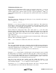
A variation of the example from Figure 7.2-1 will illustrate how easy it is to reorganize
files within a Virtual File System. The VFS Definition File shown in Figure 7.2-2
defines a Virtual File System with all files located in the VFS volume's base directory.
Note that the same source files used in Figure 7.2-1 are used again.
This example introduces several new features. It shows that the ...SRCPATH directive
can be reused to change the source directory from which source files are retrieved by the
VFS Generator.
Note that the directive ...COMPRESS is not used to disable compression before the image
files are added to the Virtual File System. Instead, the switch c- is used to disable
compression of binary files MAIN.GIF and PICTURE.JPG.
This example shows that the ...OUTFILE directive can be used multiple times to split the
resulting Virtual File System source code into more than one C file. In this case, the
Virtual File System will span two C source files, MY_HTML.C and MY_IMAGE.C, both in
directory
D:\MY_VFS on the user's development system. This feature can be very useful if
the size of the C file needed to describe your Virtual File System is very large.
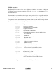
; KwikNet Virtual File System created as follows:
;
: Source file VFS file name
; ----------- -------------
; D:\MY_VFS\INDEX.HTM \INDEX.HTM
; D:\MY_VFS\HTML\MAIN.HTM \MAIN.HTM
; D:\MY_VFS\HTML\PAGE2.HTM \PAGE2.HTM
; D:\MY_VFS\HTML\PAGE3.HTM \PAGE3.HTM
; D:\MY_VFS\IMAGE\MAIN.GIF \MAIN.GIF
; D:\MY_VFS\IMAGE\PICTURE.JPG \PICTURE.JPG
; Volume information
...BASEDIR \
; File information
...COMPRESS c+
...OUTFILE D:\MY_VFS\MY_HTML.C
...SRCPATH D:\MY_VFS
...IN INDEX.HTM
...SRCPATH D:\MY_VFS\HTML
...IN MAIN.HTM
...IN PAGE2.HTM
...IN PAGE3.HTM
...OUTFILE D:\MY_VFS\MY_IMAGE.C
...SRCPATH D:\MY_VFS\IMAGE
...IN MAIN.GIF,c-
...IN PICTURE.JPG,c-
Figure 7.2-2 VFS Definition File Sample 2