
User guide


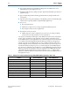
Table Of Contents
- Cyclone V Hard IP for PCI Express User Guide
- Contents
- 1. Datasheet
- 2. Getting Started with the Cyclone V Hard IP for PCI Express
- 3. Getting Started with the Avalon-MM Cyclone Hard IP for PCI Express
- Running Qsys
- Customizing the Cyclone VHard IP for PCI Express IP Core
- Adding the Remaining Components to the Qsys System
- Completing the Connections in Qsys
- Specifying Clocks and Interrupts
- Specifying Exported Interfaces
- Specifying Address Assignments
- Simulating the Example Design
- Simulating the Single DWord Design
- Understanding Channel Placement Guidelines
- Adding Synopsis Design Constraints
- Creating a Quartus II Project
- Compiling the Design
- Programming a Device
- 4. Parameter Settings for the Cyclone V Hard IP for PCI Express
- 5. Parameter Settings for the Avalon-MM Cyclone V Hard IP for PCI Express
- 6. IP Core Architecture
- Key Interfaces
- Protocol Layers
- Multi-Function Support
- PCI Express Avalon-MM Bridge
- Avalon-MM Bridge TLPs
- Avalon-MM-to-PCI Express Write Requests
- Avalon-MM-to-PCI Express Upstream Read Requests
- PCI Express-to-Avalon-MM Read Completions
- PCI Express-to-Avalon-MM Downstream Write Requests
- PCI Express-to-Avalon-MM Downstream Read Requests
- Avalon-MM-to-PCI Express Read Completions
- PCI Express-to-Avalon-MM Address Translation for Endpoints
- Minimizing BAR Sizes and the PCIe Address Space
- Avalon-MM-to-PCI Express Address Translation Algorithm
- Single DWord Completer Endpoint
- 7. IP Core Interfaces
- Cyclone V Hard IP for PCI Express
- Avalon-MM Hard IP for PCI Express
- Physical Layer Interface Signals
- Test Signals
- 8. Register Descriptions
- Configuration Space Register Content
- Altera-Defined Vendor Specific Extended Capability (VSEC)
- PCI Express Avalon-MM Bridge Control Register Access Content
- Avalon-MM to PCI Express Interrupt Registers
- PCI Express Mailbox Registers
- Avalon-MM-to-PCI Express Address Translation Table
- Root Port TLP Data Registers
- Programming Model for Avalon-MM Root Port
- PCI Express to Avalon-MM Interrupt Status and Enable Registers for Root Ports
- PCI Express to Avalon-MM Interrupt Status and Enable Registers for Endpoints
- Avalon-MM Mailbox Registers
- Correspondence between Configuration Space Registers and the PCIe Spec 2.1
- 9. Reset and Clocks
- 10. Transaction Layer Protocol (TLP) Details
- 11. Interrupts
- Interrupts for Endpoints Using the Avalon-ST Application Interface
- Interrupts for Root Ports Using the Avalon-ST Interface to the Application Layer
- Interrupts for Endpoints Using the Avalon-MM Interface to the Application Layer
- Interrupts for End Points Using the Avalon-MM Interface with Multiple MSI/MSI-X Support
- 12. Optional Features
- 13. Flow Control
- 14. Error Handling
- 15. Transceiver PHY IP Reconfiguration
- 16. SDC Timing Constraints
- 17. Testbench and Design Example
- Endpoint Testbench
- Root Port Testbench
- Chaining DMA Design Examples
- Test Driver Module
- Root Port Design Example
- Root Port BFM
- BFM Procedures and Functions
- 18. Debugging
- A. Transaction Layer Packet (TLP) Header Formats
- Additional Information
December 2013 Altera Corporation Cyclone V Hard IP for PCI Express
User Guide
1. Datasheet
This document describes the Altera
®
Cyclone
®
Hard IP for PCI Express
®
. PCI Express
is a high-performance interconnect protocol for use in a variety of applications
including network adapters, storage area networks, embedded controllers, graphic
accelerator boards, and audio-video products. The PCI Express protocol is software
backwards-compatible with the earlier PCI and PCI-X protocols, but is significantly
different from its predecessors. It is a packet-based, serial, point-to-point interconnect
between two devices. The performance is scalable based on the number of lanes and
the generation that is implemented. Altera offers a configurable hard IP block in
Cyclone V devices for both Endpoints and Root Ports that complies with the PCI
Express Base Specification 2.1. Using a configurable hard IP block, rather than
programmable logic, saves significant FPGA resources. The hard IP block is available
in ×1, ×2, and ×4 configurations. shows the aggregate bandwidth of a PCI Express link
for the available configurations. The protocol specifies 2.5 giga-transfers per second
for Gen1. provides bandwidths for a single transmit (TX) or receive (RX) channel, so
that the numbers double for duplex operation. Because the PCI Express protocol uses
8B/10B encoding, there is a 20% overhead which is included in the figures in .
Table 1–1.
f Refer to the PCI Express High Performance Reference Design for more information about
calculating bandwidth for the hard IP implementation of PCI Express in many Altera
FPGAs.
Features
The Cyclone V Hard IP for PCI Express IP supports the following key features:
■ Complete protocol stack including the Transaction, Data Link, and Physical Layers
is hardened in the device.
■ Multi-function support for up to eight Endpoint functions.
■ Support of ×1, ×2, and ×4 Gen1 and Gen2 configurations for Root Ports and
Endpoints.
■ Dedicated 6 KByte receive buffer
■ Dedicated hard reset controller
■ MegaWizard Plug-In Manager and Qsys support using the Avalon
®
Streaming
(Avalon-ST) with a 64- or 128-bit interface to the Application Layer.
Table 1–1. PCI Express Throughput
Link Width
×1 ×2 ×4
PCI Express Gen1 Gbps (2.5 Gbps) 2.5 5 10
PCI Express Gen2 Gbps (5.0 Gbps) 5 10 20
December 2013
UG-01110-1.5