
User guide
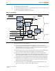
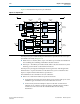
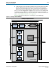
Table Of Contents
- Cyclone V Hard IP for PCI Express User Guide
- Contents
- 1. Datasheet
- 2. Getting Started with the Cyclone V Hard IP for PCI Express
- 3. Getting Started with the Avalon-MM Cyclone Hard IP for PCI Express
- Running Qsys
- Customizing the Cyclone VHard IP for PCI Express IP Core
- Adding the Remaining Components to the Qsys System
- Completing the Connections in Qsys
- Specifying Clocks and Interrupts
- Specifying Exported Interfaces
- Specifying Address Assignments
- Simulating the Example Design
- Simulating the Single DWord Design
- Understanding Channel Placement Guidelines
- Adding Synopsis Design Constraints
- Creating a Quartus II Project
- Compiling the Design
- Programming a Device
- 4. Parameter Settings for the Cyclone V Hard IP for PCI Express
- 5. Parameter Settings for the Avalon-MM Cyclone V Hard IP for PCI Express
- 6. IP Core Architecture
- Key Interfaces
- Protocol Layers
- Multi-Function Support
- PCI Express Avalon-MM Bridge
- Avalon-MM Bridge TLPs
- Avalon-MM-to-PCI Express Write Requests
- Avalon-MM-to-PCI Express Upstream Read Requests
- PCI Express-to-Avalon-MM Read Completions
- PCI Express-to-Avalon-MM Downstream Write Requests
- PCI Express-to-Avalon-MM Downstream Read Requests
- Avalon-MM-to-PCI Express Read Completions
- PCI Express-to-Avalon-MM Address Translation for Endpoints
- Minimizing BAR Sizes and the PCIe Address Space
- Avalon-MM-to-PCI Express Address Translation Algorithm
- Single DWord Completer Endpoint
- 7. IP Core Interfaces
- Cyclone V Hard IP for PCI Express
- Avalon-MM Hard IP for PCI Express
- Physical Layer Interface Signals
- Test Signals
- 8. Register Descriptions
- Configuration Space Register Content
- Altera-Defined Vendor Specific Extended Capability (VSEC)
- PCI Express Avalon-MM Bridge Control Register Access Content
- Avalon-MM to PCI Express Interrupt Registers
- PCI Express Mailbox Registers
- Avalon-MM-to-PCI Express Address Translation Table
- Root Port TLP Data Registers
- Programming Model for Avalon-MM Root Port
- PCI Express to Avalon-MM Interrupt Status and Enable Registers for Root Ports
- PCI Express to Avalon-MM Interrupt Status and Enable Registers for Endpoints
- Avalon-MM Mailbox Registers
- Correspondence between Configuration Space Registers and the PCIe Spec 2.1
- 9. Reset and Clocks
- 10. Transaction Layer Protocol (TLP) Details
- 11. Interrupts
- Interrupts for Endpoints Using the Avalon-ST Application Interface
- Interrupts for Root Ports Using the Avalon-ST Interface to the Application Layer
- Interrupts for Endpoints Using the Avalon-MM Interface to the Application Layer
- Interrupts for End Points Using the Avalon-MM Interface with Multiple MSI/MSI-X Support
- 12. Optional Features
- 13. Flow Control
- 14. Error Handling
- 15. Transceiver PHY IP Reconfiguration
- 16. SDC Timing Constraints
- 17. Testbench and Design Example
- Endpoint Testbench
- Root Port Testbench
- Chaining DMA Design Examples
- Test Driver Module
- Root Port Design Example
- Root Port BFM
- BFM Procedures and Functions
- 18. Debugging
- A. Transaction Layer Packet (TLP) Header Formats
- Additional Information

6–14 Chapter 6: IP Core Architecture
Avalon-MM Bridge TLPs
Cyclone V Hard IP for PCI Express December 2013 Altera Corporation
User Guide
The bridge has the following additional characteristics:
■ Type 0 and Type 1 vendor-defined incoming messages are discarded
■ Completion-to-a-flush request is generated, but not propagated to the interconnect
fabric
For End Points, each PCI Express base address register (BAR) in the Transaction Layer
maps to a specific, fixed Avalon-MM address range. You can use separate BARs to
map to various Avalon-MM slaves connected to the RX Master port. In contrast to
Endpoints, Root Ports do not perform any BAR matching and forwards the address to
a single RX Avalon-MM master port.
Avalon-MM Bridge TLPs
The PCI Express to Avalon-MM bridge translates the PCI Express read, write, and
completion Transaction Layer Packets (TLPs) into standard Avalon-MM read and
write commands typically used by master and slave interfaces. This PCI Express to
Avalon-MM bridge also translates Avalon-MM read, write and read data commands
to PCI Express read, write and completion TLPs. The following functions are
available:
■ Avalon-MM-to-PCI Express Write Requests
■ Avalon-MM-to-PCI Express Upstream Read Requests
■ PCI Express-to-Avalon-MM Read Completions
■ PCI Express-to-Avalon-MM Downstream Write Requests
■ PCI Express-to-Avalon-MM Downstream Read Requests
■ PCI Express-to-Avalon-MM Read Completions
■ PCI Express-to-Avalon-MM Address Translation for Endpoints
■ Avalon-MM-to-PCI Express Address Translation Algorithm
Avalon-MM-to-PCI Express Write Requests
The Avalon-MM bridge accepts Avalon-MM burst write requests with a burst size of
up to 512 Bytes at the Avalon-MM TX slave interface. The Avalon-MM bridge
converts the write requests to one or more PCI Express write packets with 32– or
64-bit addresses based on the address translation configuration, the request address,
and the maximum payload size.
The Avalon-MM write requests can start on any address in the range defined in the
PCI Express address table parameters. The bridge splits incoming burst writes that
cross a 4 KByte boundary into at least two separate PCI Express packets. The bridge
also considers the root complex requirement for maximum payload on the PCI
Express side by further segmenting the packets if needed.
The bridge requires Avalon-MM write requests with a burst count of greater than one
to adhere to the following byte enable rules:
■ The Avalon-MM byte enables must be asserted in the first qword of the burst.
■ All subsequent byte enables must be asserted until the deasserting byte enable.