
User guide
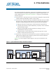
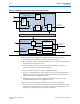
Table Of Contents
- Cyclone V Hard IP for PCI Express User Guide
- Contents
- 1. Datasheet
- 2. Getting Started with the Cyclone V Hard IP for PCI Express
- 3. Getting Started with the Avalon-MM Cyclone Hard IP for PCI Express
- Running Qsys
- Customizing the Cyclone VHard IP for PCI Express IP Core
- Adding the Remaining Components to the Qsys System
- Completing the Connections in Qsys
- Specifying Clocks and Interrupts
- Specifying Exported Interfaces
- Specifying Address Assignments
- Simulating the Example Design
- Simulating the Single DWord Design
- Understanding Channel Placement Guidelines
- Adding Synopsis Design Constraints
- Creating a Quartus II Project
- Compiling the Design
- Programming a Device
- 4. Parameter Settings for the Cyclone V Hard IP for PCI Express
- 5. Parameter Settings for the Avalon-MM Cyclone V Hard IP for PCI Express
- 6. IP Core Architecture
- Key Interfaces
- Protocol Layers
- Multi-Function Support
- PCI Express Avalon-MM Bridge
- Avalon-MM Bridge TLPs
- Avalon-MM-to-PCI Express Write Requests
- Avalon-MM-to-PCI Express Upstream Read Requests
- PCI Express-to-Avalon-MM Read Completions
- PCI Express-to-Avalon-MM Downstream Write Requests
- PCI Express-to-Avalon-MM Downstream Read Requests
- Avalon-MM-to-PCI Express Read Completions
- PCI Express-to-Avalon-MM Address Translation for Endpoints
- Minimizing BAR Sizes and the PCIe Address Space
- Avalon-MM-to-PCI Express Address Translation Algorithm
- Single DWord Completer Endpoint
- 7. IP Core Interfaces
- Cyclone V Hard IP for PCI Express
- Avalon-MM Hard IP for PCI Express
- Physical Layer Interface Signals
- Test Signals
- 8. Register Descriptions
- Configuration Space Register Content
- Altera-Defined Vendor Specific Extended Capability (VSEC)
- PCI Express Avalon-MM Bridge Control Register Access Content
- Avalon-MM to PCI Express Interrupt Registers
- PCI Express Mailbox Registers
- Avalon-MM-to-PCI Express Address Translation Table
- Root Port TLP Data Registers
- Programming Model for Avalon-MM Root Port
- PCI Express to Avalon-MM Interrupt Status and Enable Registers for Root Ports
- PCI Express to Avalon-MM Interrupt Status and Enable Registers for Endpoints
- Avalon-MM Mailbox Registers
- Correspondence between Configuration Space Registers and the PCIe Spec 2.1
- 9. Reset and Clocks
- 10. Transaction Layer Protocol (TLP) Details
- 11. Interrupts
- Interrupts for Endpoints Using the Avalon-ST Application Interface
- Interrupts for Root Ports Using the Avalon-ST Interface to the Application Layer
- Interrupts for Endpoints Using the Avalon-MM Interface to the Application Layer
- Interrupts for End Points Using the Avalon-MM Interface with Multiple MSI/MSI-X Support
- 12. Optional Features
- 13. Flow Control
- 14. Error Handling
- 15. Transceiver PHY IP Reconfiguration
- 16. SDC Timing Constraints
- 17. Testbench and Design Example
- Endpoint Testbench
- Root Port Testbench
- Chaining DMA Design Examples
- Test Driver Module
- Root Port Design Example
- Root Port BFM
- BFM Procedures and Functions
- 18. Debugging
- A. Transaction Layer Packet (TLP) Header Formats
- Additional Information
6–6 Chapter 6: IP Core Architecture
Protocol Layers
Cyclone V Hard IP for PCI Express December 2013 Altera Corporation
User Guide
Tracing a transaction through the RX datapath includes the following steps:
1. The Transaction Layer receives a TLP from the Data Link Layer.
2. The Configuration Space determines whether the TLP is well formed and directs
the packet based on traffic class (TC).
3. TLPs are stored in a specific part of the RX buffer depending on the type of
transaction (posted, non-posted, and completion).
4. The TLP FIFO block stores the address of the buffered TLP.
5. The receive reordering block reorders the queue of TLPs as needed, fetches the
address of the highest priority TLP from the TLP FIFO block, and initiates the
transfer of the TLP to the Application Layer.
6. When ECRC generation and forwarding are enabled, the Transaction Layer
forwards the ECRC dword to the Application Layer.
Tracing a transaction through the TX datapath involves the following steps:
1. The Transaction Layer informs the Application Layer that sufficient flow control
credits exist for a particular type of transaction using the TX credit signals. The
Application Layer may choose to ignore this information.
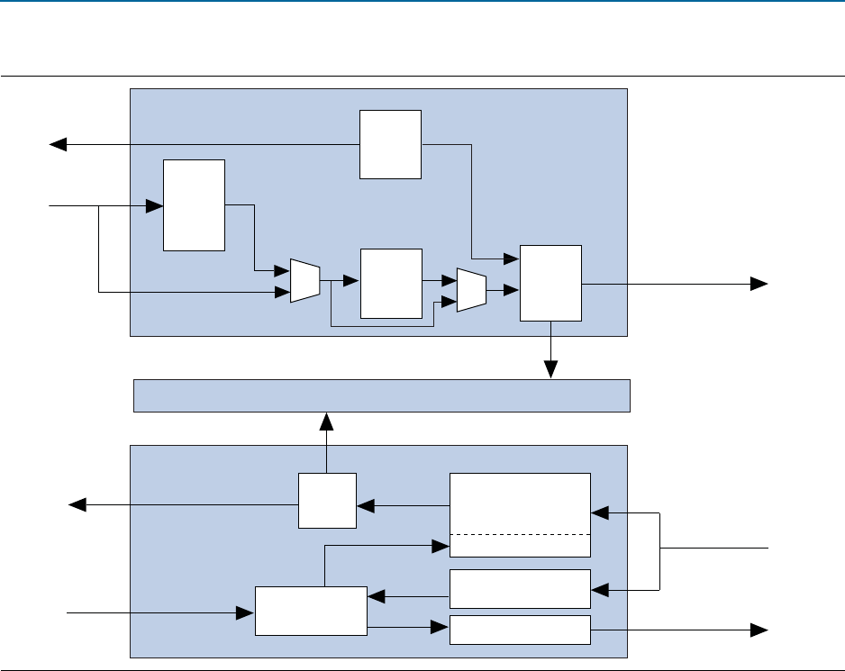
Figure 6–3. Architecture of the Transaction Layer: Dedicated Receive Buffer
Transaction Layer TX Datapath
Transaction Layer RX Datapath
Avalon-ST
RX Control
Configuration Space
TLPs to
Data Link Layer
RX Transaction
Layer Packet
Avalon-ST RX Data
Avalon-ST
TX Data
to Application Layer
Configuration Requests
Reordering
RX Buffer
Posted & Completion
Non-Posted
Flow Control Update
Transaction Layer
Packet FIFO
Width
Adapter
( <256
bits)
Packet
Alignment
TX
Control
RX
Control
TX Flow
Control