
User guide


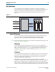


Table Of Contents
- Cyclone V Hard IP for PCI Express User Guide
- Contents
- 1. Datasheet
- 2. Getting Started with the Cyclone V Hard IP for PCI Express
- 3. Getting Started with the Avalon-MM Cyclone Hard IP for PCI Express
- Running Qsys
- Customizing the Cyclone VHard IP for PCI Express IP Core
- Adding the Remaining Components to the Qsys System
- Completing the Connections in Qsys
- Specifying Clocks and Interrupts
- Specifying Exported Interfaces
- Specifying Address Assignments
- Simulating the Example Design
- Simulating the Single DWord Design
- Understanding Channel Placement Guidelines
- Adding Synopsis Design Constraints
- Creating a Quartus II Project
- Compiling the Design
- Programming a Device
- 4. Parameter Settings for the Cyclone V Hard IP for PCI Express
- 5. Parameter Settings for the Avalon-MM Cyclone V Hard IP for PCI Express
- 6. IP Core Architecture
- Key Interfaces
- Protocol Layers
- Multi-Function Support
- PCI Express Avalon-MM Bridge
- Avalon-MM Bridge TLPs
- Avalon-MM-to-PCI Express Write Requests
- Avalon-MM-to-PCI Express Upstream Read Requests
- PCI Express-to-Avalon-MM Read Completions
- PCI Express-to-Avalon-MM Downstream Write Requests
- PCI Express-to-Avalon-MM Downstream Read Requests
- Avalon-MM-to-PCI Express Read Completions
- PCI Express-to-Avalon-MM Address Translation for Endpoints
- Minimizing BAR Sizes and the PCIe Address Space
- Avalon-MM-to-PCI Express Address Translation Algorithm
- Single DWord Completer Endpoint
- 7. IP Core Interfaces
- Cyclone V Hard IP for PCI Express
- Avalon-MM Hard IP for PCI Express
- Physical Layer Interface Signals
- Test Signals
- 8. Register Descriptions
- Configuration Space Register Content
- Altera-Defined Vendor Specific Extended Capability (VSEC)
- PCI Express Avalon-MM Bridge Control Register Access Content
- Avalon-MM to PCI Express Interrupt Registers
- PCI Express Mailbox Registers
- Avalon-MM-to-PCI Express Address Translation Table
- Root Port TLP Data Registers
- Programming Model for Avalon-MM Root Port
- PCI Express to Avalon-MM Interrupt Status and Enable Registers for Root Ports
- PCI Express to Avalon-MM Interrupt Status and Enable Registers for Endpoints
- Avalon-MM Mailbox Registers
- Correspondence between Configuration Space Registers and the PCIe Spec 2.1
- 9. Reset and Clocks
- 10. Transaction Layer Protocol (TLP) Details
- 11. Interrupts
- Interrupts for Endpoints Using the Avalon-ST Application Interface
- Interrupts for Root Ports Using the Avalon-ST Interface to the Application Layer
- Interrupts for Endpoints Using the Avalon-MM Interface to the Application Layer
- Interrupts for End Points Using the Avalon-MM Interface with Multiple MSI/MSI-X Support
- 12. Optional Features
- 13. Flow Control
- 14. Error Handling
- 15. Transceiver PHY IP Reconfiguration
- 16. SDC Timing Constraints
- 17. Testbench and Design Example
- Endpoint Testbench
- Root Port Testbench
- Chaining DMA Design Examples
- Test Driver Module
- Root Port Design Example
- Root Port BFM
- BFM Procedures and Functions
- 18. Debugging
- A. Transaction Layer Packet (TLP) Header Formats
- Additional Information

Chapter 6: IP Core Architecture 6–5
Protocol Layers
December 2013 Altera Corporation Cyclone V Hard IP for PCI Express
User Guide
Transceiver Reconfiguration
The transceiver reconfiguration interface allows you to dynamically reconfigure the
values of analog settings in the PMA block of the transceiver. Dynamic
reconfiguration is necessary to compensate for process variations. The Altera
Transceiver Reconfiguration Controller IP core provides access to these analog
settings. This component is included in the example designs in the
<install_dir>/ip/altera/altera_pcie/altera_pcie_hip_ast_ed/
example_design directory. For more information about the transceiver
reconfiguration interface, refer to “Transceiver Reconfiguration” on page 7–47.
Interrupts
The Cyclone V Hard IP for PCI Express offers three interrupt mechanisms:
■ Message Signaled Interrupts (MSI)— MSI uses the Transaction Layer's
request-acknowledge handshaking protocol to implement interrupts. The MSI
Capability structure is stored in the Configuration Space and is programmable
using Configuration Space accesses.
■ MSI-X—The Transaction Layer generates MSI-X messages which are single dword
memory writes. In contrast to the MSI capability structure, which contains all of
the control and status information for the interrupt vectors, the MSI-X Capability
structure points to an MSI-X table structure and MSI-X PBA structure which are
stored in memory.
■ Legacy interrupts—The
app_int_sts
input port controls legacy interrupt
generation. When
app_int_sts
is asserted, the Hard IP generates an
Assert_INT<n> message TLP. For more detailed information about interrupts,
refer to “Interrupt Signals for Endpoints” on page 7–27.
PIPE
The PIPE interface implements the Intel-designed PIPE interface specification. You
can use this parallel interface to speed simulation; however, you cannot use the PIPE
interface in actual hardware. The Gen1 and Gen2 simulation models support pipe and
serial simulation.
Protocol Layers
This section describes the Transaction Layer, Data Link Layer, and Physical Layer in
more detail.
Transaction Layer
The Transaction Layer is located between the Application Layer and the Data Link
Layer. It generates and receives Transaction Layer Packets.
Figure 6–3 illustrates the Transaction Layer. As Figure 6–3 illustrates, the Transaction
Layer includes three sub-blocks: the TX datapath, the Configuration Space, and the
RX datapath.