
User guide
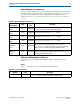
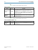
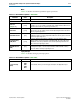


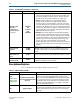
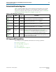
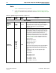
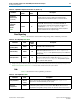

Table Of Contents
- Cyclone V Hard IP for PCI Express User Guide
- Contents
- 1. Datasheet
- 2. Getting Started with the Cyclone V Hard IP for PCI Express
- 3. Getting Started with the Avalon-MM Cyclone Hard IP for PCI Express
- Running Qsys
- Customizing the Cyclone VHard IP for PCI Express IP Core
- Adding the Remaining Components to the Qsys System
- Completing the Connections in Qsys
- Specifying Clocks and Interrupts
- Specifying Exported Interfaces
- Specifying Address Assignments
- Simulating the Example Design
- Simulating the Single DWord Design
- Understanding Channel Placement Guidelines
- Adding Synopsis Design Constraints
- Creating a Quartus II Project
- Compiling the Design
- Programming a Device
- 4. Parameter Settings for the Cyclone V Hard IP for PCI Express
- 5. Parameter Settings for the Avalon-MM Cyclone V Hard IP for PCI Express
- 6. IP Core Architecture
- Key Interfaces
- Protocol Layers
- Multi-Function Support
- PCI Express Avalon-MM Bridge
- Avalon-MM Bridge TLPs
- Avalon-MM-to-PCI Express Write Requests
- Avalon-MM-to-PCI Express Upstream Read Requests
- PCI Express-to-Avalon-MM Read Completions
- PCI Express-to-Avalon-MM Downstream Write Requests
- PCI Express-to-Avalon-MM Downstream Read Requests
- Avalon-MM-to-PCI Express Read Completions
- PCI Express-to-Avalon-MM Address Translation for Endpoints
- Minimizing BAR Sizes and the PCIe Address Space
- Avalon-MM-to-PCI Express Address Translation Algorithm
- Single DWord Completer Endpoint
- 7. IP Core Interfaces
- Cyclone V Hard IP for PCI Express
- Avalon-MM Hard IP for PCI Express
- Physical Layer Interface Signals
- Test Signals
- 8. Register Descriptions
- Configuration Space Register Content
- Altera-Defined Vendor Specific Extended Capability (VSEC)
- PCI Express Avalon-MM Bridge Control Register Access Content
- Avalon-MM to PCI Express Interrupt Registers
- PCI Express Mailbox Registers
- Avalon-MM-to-PCI Express Address Translation Table
- Root Port TLP Data Registers
- Programming Model for Avalon-MM Root Port
- PCI Express to Avalon-MM Interrupt Status and Enable Registers for Root Ports
- PCI Express to Avalon-MM Interrupt Status and Enable Registers for Endpoints
- Avalon-MM Mailbox Registers
- Correspondence between Configuration Space Registers and the PCIe Spec 2.1
- 9. Reset and Clocks
- 10. Transaction Layer Protocol (TLP) Details
- 11. Interrupts
- Interrupts for Endpoints Using the Avalon-ST Application Interface
- Interrupts for Root Ports Using the Avalon-ST Interface to the Application Layer
- Interrupts for Endpoints Using the Avalon-MM Interface to the Application Layer
- Interrupts for End Points Using the Avalon-MM Interface with Multiple MSI/MSI-X Support
- 12. Optional Features
- 13. Flow Control
- 14. Error Handling
- 15. Transceiver PHY IP Reconfiguration
- 16. SDC Timing Constraints
- 17. Testbench and Design Example
- Endpoint Testbench
- Root Port Testbench
- Chaining DMA Design Examples
- Test Driver Module
- Root Port Design Example
- Root Port BFM
- BFM Procedures and Functions
- 18. Debugging
- A. Transaction Layer Packet (TLP) Header Formats
- Additional Information

5–2 Chapter 5: Parameter Settings for the Avalon-MM Cyclone V Hard IP for PCI Express
Base Address Registers
Cyclone V Hard IP for PCI Express December 2013 Altera Corporation
User Guide
Base Address Registers
Table 5–2 describes the Base Address (BAR) register parameters.
RX Buffer credit
allocation -
performance for
received requests
(continued)
Minimum
Low
Balanced
High
Maximum
■ Balanced–This setting allocates approximately half the RX Buffer
space to received requests and the other half of the RX Buffer space
to received completions. Select this option for variations where the
received requests and received completions are roughly equal.
■ High–This setting configures most of the RX Buffer space for
received requests and allocates a slightly larger than minimum
amount of space for received completions. Select this option when
most of the PCIe requests are generated by the other end of the PCIe
link and the local application layer logic only infrequently generates a
small burst of read requests. This option is recommended for typical
root port applications where most of the PCIe traffic is generated by
DMA engines located in the endpoints.
■ Maximum–This setting configures the minimum PCIe specification
allowed amount of completion space, leaving most of the RX Buffer
space for received requests. Select this option when most of the PCIe
requests are generated by the other end of the PCIe link and the local
Application Layer never or only infrequently generates single read
requests. This option is recommended for control and status
endpoint applications that do not generate any PCIe requests of their
own and only are the target of write and read requests from the Root
Complex.
Reference clock
frequency
100 MHz
125 MHz
The
PCI Express Base Specification 2.1 requires a
100 MHz
300 ppm reference clock. The 125 MHz reference clock is
provided as a convenience for systems that include a 125 MHz clock
source.
Use 62.5 MHz
Application Layer
clock
On/Off This is a special power saving mode available only for Gen1 ×1 variants.
Enable configuration
via the PCIe link
On/Off
When On, the Quartus II software places the Endpoint in the location
required for configuration via protocol (CvP).
Table 5–1. System Settings for PCI Express (Part 2 of 2)
Parameter Value Description
Table 5–2. BARs and Expansion ROM
Parameter Value Description
Type
0x010, 0x014,
0x018, 0x01C,
0x020, 0x024
64-bit prefetchable memory
32-bit non-prefetchable memory
Not used
If you select 64-bit prefetchable memory, 2 contiguous BARs are
combined to form a 64-bit prefetchable BAR; you must set the
higher numbered BAR to Disabled. A non-prefetchable 64-bit BAR
is not supported because in a typical system, the Root Port Type 1
Configuration Space sets the maximum non-prefetchable memory
window to 32-bits. The BARs can also be configured as separate
32-bit non-prefetchable memories.
Size 16 Bytes–8 EBytes
Specifies the number of address bits required for address
translation. Qsys automatically calculates the BAR Size based on the
address range specified in your Qsys system. You cannot change
this value.