
User guide
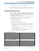
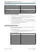

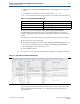
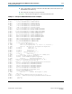
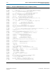
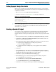
Table Of Contents
- Cyclone V Hard IP for PCI Express User Guide
- Contents
- 1. Datasheet
- 2. Getting Started with the Cyclone V Hard IP for PCI Express
- 3. Getting Started with the Avalon-MM Cyclone Hard IP for PCI Express
- Running Qsys
- Customizing the Cyclone VHard IP for PCI Express IP Core
- Adding the Remaining Components to the Qsys System
- Completing the Connections in Qsys
- Specifying Clocks and Interrupts
- Specifying Exported Interfaces
- Specifying Address Assignments
- Simulating the Example Design
- Simulating the Single DWord Design
- Understanding Channel Placement Guidelines
- Adding Synopsis Design Constraints
- Creating a Quartus II Project
- Compiling the Design
- Programming a Device
- 4. Parameter Settings for the Cyclone V Hard IP for PCI Express
- 5. Parameter Settings for the Avalon-MM Cyclone V Hard IP for PCI Express
- 6. IP Core Architecture
- Key Interfaces
- Protocol Layers
- Multi-Function Support
- PCI Express Avalon-MM Bridge
- Avalon-MM Bridge TLPs
- Avalon-MM-to-PCI Express Write Requests
- Avalon-MM-to-PCI Express Upstream Read Requests
- PCI Express-to-Avalon-MM Read Completions
- PCI Express-to-Avalon-MM Downstream Write Requests
- PCI Express-to-Avalon-MM Downstream Read Requests
- Avalon-MM-to-PCI Express Read Completions
- PCI Express-to-Avalon-MM Address Translation for Endpoints
- Minimizing BAR Sizes and the PCIe Address Space
- Avalon-MM-to-PCI Express Address Translation Algorithm
- Single DWord Completer Endpoint
- 7. IP Core Interfaces
- Cyclone V Hard IP for PCI Express
- Avalon-MM Hard IP for PCI Express
- Physical Layer Interface Signals
- Test Signals
- 8. Register Descriptions
- Configuration Space Register Content
- Altera-Defined Vendor Specific Extended Capability (VSEC)
- PCI Express Avalon-MM Bridge Control Register Access Content
- Avalon-MM to PCI Express Interrupt Registers
- PCI Express Mailbox Registers
- Avalon-MM-to-PCI Express Address Translation Table
- Root Port TLP Data Registers
- Programming Model for Avalon-MM Root Port
- PCI Express to Avalon-MM Interrupt Status and Enable Registers for Root Ports
- PCI Express to Avalon-MM Interrupt Status and Enable Registers for Endpoints
- Avalon-MM Mailbox Registers
- Correspondence between Configuration Space Registers and the PCIe Spec 2.1
- 9. Reset and Clocks
- 10. Transaction Layer Protocol (TLP) Details
- 11. Interrupts
- Interrupts for Endpoints Using the Avalon-ST Application Interface
- Interrupts for Root Ports Using the Avalon-ST Interface to the Application Layer
- Interrupts for Endpoints Using the Avalon-MM Interface to the Application Layer
- Interrupts for End Points Using the Avalon-MM Interface with Multiple MSI/MSI-X Support
- 12. Optional Features
- 13. Flow Control
- 14. Error Handling
- 15. Transceiver PHY IP Reconfiguration
- 16. SDC Timing Constraints
- 17. Testbench and Design Example
- Endpoint Testbench
- Root Port Testbench
- Chaining DMA Design Examples
- Test Driver Module
- Root Port Design Example
- Root Port BFM
- BFM Procedures and Functions
- 18. Debugging
- A. Transaction Layer Packet (TLP) Header Formats
- Additional Information

Chapter 3: Getting Started with the Avalon-MM Cyclone Hard IP for PCI Express 3–15
Simulating the Single DWord Design
December 2013 Altera Corporation Cyclone V Hard IP for PCI Express
User Guide
Simulating the Single DWord Design
You can use the same testbench to simulate the Completer-Only single dword IP core
by changing the settings in the driver file. Complete the following steps for the
Verilog HDL design example:
1. In a terminal window, change to the <project_dir>/<variant>/testbench/
<variant>_tb/simulation/submodules directory.
2. Open altpcietb_bfm_driver_avmm.v file your text editor.
3. To enable target memory tests and specify the completer-only single dword
variant, specify the following parameters:
■
parameter RUN_TGT_MEM_TST = 1;
■
parameter RUN_DMA_MEM_TST = 0;
■
parameter AVALON_MM_LITE = 1;
4. Change to the <project_dir>/<variant>/testbench/mentor directory.
5. Start the ModelSim simulator.
6. To run the simulation, type the following commands in a terminal window:
a.
do msim_setup.tcl
r
b. ld_debug
r (The -debug suffix stops optimizations, improving visibility in the
ModelSim waveforms.)
c. run 140000 ns
r
Understanding Channel Placement Guidelines
Refer to “Channel Placement for ×1 Variants” on page 7–48 for more information
about channel placement for ×1 and ×4 variants.
f For more information about Cyclone V transceivers refer to the “PCIe Supported
Configurations and Placement Guides” section in the Transceiver Protocol
Configurations in Cyclone V Devices.
Example 3–1. Transcript from ModelSim Simulation of Gen1 x4 Endpoint (continued)
# INFO: 54368 ns Setup BAR = 2
# INFO: 54368 ns Length = 000512, Start Offset = 000000
# INFO: 60609 ns Interrupt Monitor: Interrupt INTA Asserted
# INFO: 60609 ns Clear Interrupt INTA
# INF
O: 62225 ns Interrupt Monitor: Interrupt INTA Deasserted
# INFO: 69361 ns MSI recieved!
# INFO: 69361 ns DMA Read
and Write compared okay!
# SUCCESS: Simulation stopped due to successful completion!
# Break at ./..//ep_g1x4_tb/simulation/submodules//altpcietb_bfm_log.v line 78