
User guide
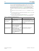
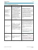
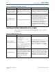
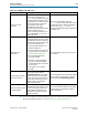
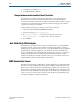
Table Of Contents
- Cyclone V Hard IP for PCI Express User Guide
- Contents
- 1. Datasheet
- 2. Getting Started with the Cyclone V Hard IP for PCI Express
- 3. Getting Started with the Avalon-MM Cyclone Hard IP for PCI Express
- Running Qsys
- Customizing the Cyclone VHard IP for PCI Express IP Core
- Adding the Remaining Components to the Qsys System
- Completing the Connections in Qsys
- Specifying Clocks and Interrupts
- Specifying Exported Interfaces
- Specifying Address Assignments
- Simulating the Example Design
- Simulating the Single DWord Design
- Understanding Channel Placement Guidelines
- Adding Synopsis Design Constraints
- Creating a Quartus II Project
- Compiling the Design
- Programming a Device
- 4. Parameter Settings for the Cyclone V Hard IP for PCI Express
- 5. Parameter Settings for the Avalon-MM Cyclone V Hard IP for PCI Express
- 6. IP Core Architecture
- Key Interfaces
- Protocol Layers
- Multi-Function Support
- PCI Express Avalon-MM Bridge
- Avalon-MM Bridge TLPs
- Avalon-MM-to-PCI Express Write Requests
- Avalon-MM-to-PCI Express Upstream Read Requests
- PCI Express-to-Avalon-MM Read Completions
- PCI Express-to-Avalon-MM Downstream Write Requests
- PCI Express-to-Avalon-MM Downstream Read Requests
- Avalon-MM-to-PCI Express Read Completions
- PCI Express-to-Avalon-MM Address Translation for Endpoints
- Minimizing BAR Sizes and the PCIe Address Space
- Avalon-MM-to-PCI Express Address Translation Algorithm
- Single DWord Completer Endpoint
- 7. IP Core Interfaces
- Cyclone V Hard IP for PCI Express
- Avalon-MM Hard IP for PCI Express
- Physical Layer Interface Signals
- Test Signals
- 8. Register Descriptions
- Configuration Space Register Content
- Altera-Defined Vendor Specific Extended Capability (VSEC)
- PCI Express Avalon-MM Bridge Control Register Access Content
- Avalon-MM to PCI Express Interrupt Registers
- PCI Express Mailbox Registers
- Avalon-MM-to-PCI Express Address Translation Table
- Root Port TLP Data Registers
- Programming Model for Avalon-MM Root Port
- PCI Express to Avalon-MM Interrupt Status and Enable Registers for Root Ports
- PCI Express to Avalon-MM Interrupt Status and Enable Registers for Endpoints
- Avalon-MM Mailbox Registers
- Correspondence between Configuration Space Registers and the PCIe Spec 2.1
- 9. Reset and Clocks
- 10. Transaction Layer Protocol (TLP) Details
- 11. Interrupts
- Interrupts for Endpoints Using the Avalon-ST Application Interface
- Interrupts for Root Ports Using the Avalon-ST Interface to the Application Layer
- Interrupts for Endpoints Using the Avalon-MM Interface to the Application Layer
- Interrupts for End Points Using the Avalon-MM Interface with Multiple MSI/MSI-X Support
- 12. Optional Features
- 13. Flow Control
- 14. Error Handling
- 15. Transceiver PHY IP Reconfiguration
- 16. SDC Timing Constraints
- 17. Testbench and Design Example
- Endpoint Testbench
- Root Port Testbench
- Chaining DMA Design Examples
- Test Driver Module
- Root Port Design Example
- Root Port BFM
- BFM Procedures and Functions
- 18. Debugging
- A. Transaction Layer Packet (TLP) Header Formats
- Additional Information

18–4 Chapter 18: Debugging
Link Hangs in L0 Due To Deassertion of tx_st_ready
Cyclone V Hard IP for PCI Express December 2013 Altera Corporation
User Guide
Link Hangs in L0 Due To Deassertion of tx_st_ready
There are many reasons that link may stop transmitting data. Table 18–2 lists some
possible causes.
Link fails because LTSSM
state machine unexpectedly
transitions to Recovery
A framing error is detected on the link
causing LTSSM to enter the Recovery
state.
In simulation, set
test_in[1]
=1 to speed up
simulation. This solution only solves this problem
for simulation. For hardware, customer must set
test_in[1]
=0.
Gen2 variants fail to link
when plugged into Gen3
slots
Gen2 design fails to link in Gen3 slots.
Two workarounds address this issue:
■ Modify the BIOS of the Root Port to be capable
of coming up at the Gen2 data rate. After you
implement this workaround, the slot can
support either Gen1 or Gen2 only. Using this
setting, the link will train up to Gen2.
■ If this BIOS option is not available for the Root
Port, regenerate the variant to support a
maximum data rate of Gen1. With this
configuration, the link will come up in the Gen1
data rate.
Table 18–1. Link Training Fails to Reach L0 (Part 3 of 3)
Possible Causes Symptoms and Root Causes Workarounds and Solutions
Table 18–2. Link Hangs in L0 (Part 1 of 2)
Possible Causes Symptoms and Root Causes Workarounds and Solutions
Avalon-ST signalling
violates Avalon-ST protocol
Avalon-ST protocol violations include
the following errors:
■ More than one
tx_st_sop
per
tx_st_eop
.
■ Two or more
tx_st_eop’s
without
a corresponding
tx_st_sop.
■
rx_st_valid
is not asserted with
tx_st_sop
or
tx_st_eop
.
These errors are applicable to both
simulation and hardware.
Add logic to detect situations where
tx_st_ready
remains deasserted for more than 100 cycles. Set
post-triggering conditions to check for the
Avalon-ST signalling of last two TLPs to verify
correct
tx_st_sop
and
tx_st_eop
signalling.
Incorrect payload size
Determine if the length field of the last
TLP transmitted by End Point is greater
than the InitFC credit advertised by the
link partner. For simulation, refer to the
log file and simulation dump. For
hardware, use a third-party logic
analyzer trace to capture PCIe
transactions.
If the payload is greater than the initFC credit
advertised, you must either increase the InitFC of
the posted request to be greater than the max
payload size or reduce the payload size of the
requested TLP to be less than the InitFC value.