
User guide
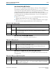
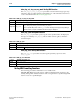
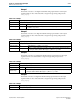
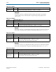
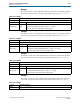
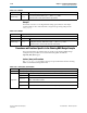
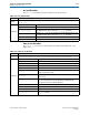
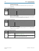
Table Of Contents
- Cyclone V Hard IP for PCI Express User Guide
- Contents
- 1. Datasheet
- 2. Getting Started with the Cyclone V Hard IP for PCI Express
- 3. Getting Started with the Avalon-MM Cyclone Hard IP for PCI Express
- Running Qsys
- Customizing the Cyclone VHard IP for PCI Express IP Core
- Adding the Remaining Components to the Qsys System
- Completing the Connections in Qsys
- Specifying Clocks and Interrupts
- Specifying Exported Interfaces
- Specifying Address Assignments
- Simulating the Example Design
- Simulating the Single DWord Design
- Understanding Channel Placement Guidelines
- Adding Synopsis Design Constraints
- Creating a Quartus II Project
- Compiling the Design
- Programming a Device
- 4. Parameter Settings for the Cyclone V Hard IP for PCI Express
- 5. Parameter Settings for the Avalon-MM Cyclone V Hard IP for PCI Express
- 6. IP Core Architecture
- Key Interfaces
- Protocol Layers
- Multi-Function Support
- PCI Express Avalon-MM Bridge
- Avalon-MM Bridge TLPs
- Avalon-MM-to-PCI Express Write Requests
- Avalon-MM-to-PCI Express Upstream Read Requests
- PCI Express-to-Avalon-MM Read Completions
- PCI Express-to-Avalon-MM Downstream Write Requests
- PCI Express-to-Avalon-MM Downstream Read Requests
- Avalon-MM-to-PCI Express Read Completions
- PCI Express-to-Avalon-MM Address Translation for Endpoints
- Minimizing BAR Sizes and the PCIe Address Space
- Avalon-MM-to-PCI Express Address Translation Algorithm
- Single DWord Completer Endpoint
- 7. IP Core Interfaces
- Cyclone V Hard IP for PCI Express
- Avalon-MM Hard IP for PCI Express
- Physical Layer Interface Signals
- Test Signals
- 8. Register Descriptions
- Configuration Space Register Content
- Altera-Defined Vendor Specific Extended Capability (VSEC)
- PCI Express Avalon-MM Bridge Control Register Access Content
- Avalon-MM to PCI Express Interrupt Registers
- PCI Express Mailbox Registers
- Avalon-MM-to-PCI Express Address Translation Table
- Root Port TLP Data Registers
- Programming Model for Avalon-MM Root Port
- PCI Express to Avalon-MM Interrupt Status and Enable Registers for Root Ports
- PCI Express to Avalon-MM Interrupt Status and Enable Registers for Endpoints
- Avalon-MM Mailbox Registers
- Correspondence between Configuration Space Registers and the PCIe Spec 2.1
- 9. Reset and Clocks
- 10. Transaction Layer Protocol (TLP) Details
- 11. Interrupts
- Interrupts for Endpoints Using the Avalon-ST Application Interface
- Interrupts for Root Ports Using the Avalon-ST Interface to the Application Layer
- Interrupts for Endpoints Using the Avalon-MM Interface to the Application Layer
- Interrupts for End Points Using the Avalon-MM Interface with Multiple MSI/MSI-X Support
- 12. Optional Features
- 13. Flow Control
- 14. Error Handling
- 15. Transceiver PHY IP Reconfiguration
- 16. SDC Timing Constraints
- 17. Testbench and Design Example
- Endpoint Testbench
- Root Port Testbench
- Chaining DMA Design Examples
- Test Driver Module
- Root Port Design Example
- Root Port BFM
- BFM Procedures and Functions
- 18. Debugging
- A. Transaction Layer Packet (TLP) Header Formats
- Additional Information
17–44 Chapter 17: Testbench and Design Example
BFM Procedures and Functions
Cyclone V Hard IP for PCI Express December 2013 Altera Corporation
User Guide
dimage7
This function creates a seven-digit decimal string representation of the input
argument that can be concatenated into a larger message string and passed to
ebfm_display
.
Procedures and Functions Specific to the Chaining DMA Design Example
This section describes procedures that are specific to the chaining DMA design
example. These procedures are located in the Verilog HDL module file
altpcietb_bfm_driver_rp.v.
chained_dma_test Procedure
The
chained_dma_test
procedure is the top-level procedure that runs the chaining
DMA read and the chaining DMA write
Argument range
vec
Input data type
reg
with a
range
of 31:0.
Return range
string
Returns a 6-digit decimal representation of the input argument that is padded with leading
0s if necessary. Return data is type
reg
with a
range
of 48:1.
Returns the letter U if the value cannot be represented.
Table 17–53. dimage6
Table 17–54. dimage7
Location altpcietb_bfm_log.v
syntax
string:= dimage(vec)
Argument range
vec
Input data type
reg
with a
range
of 31:0.
Return range
string
Returns a 7-digit decimal representation of the input argument that is padded with
leading 0s if necessary. Return data is type
reg
with a
range
of 56:1.
Returns the letter <U> if the value cannot be represented.
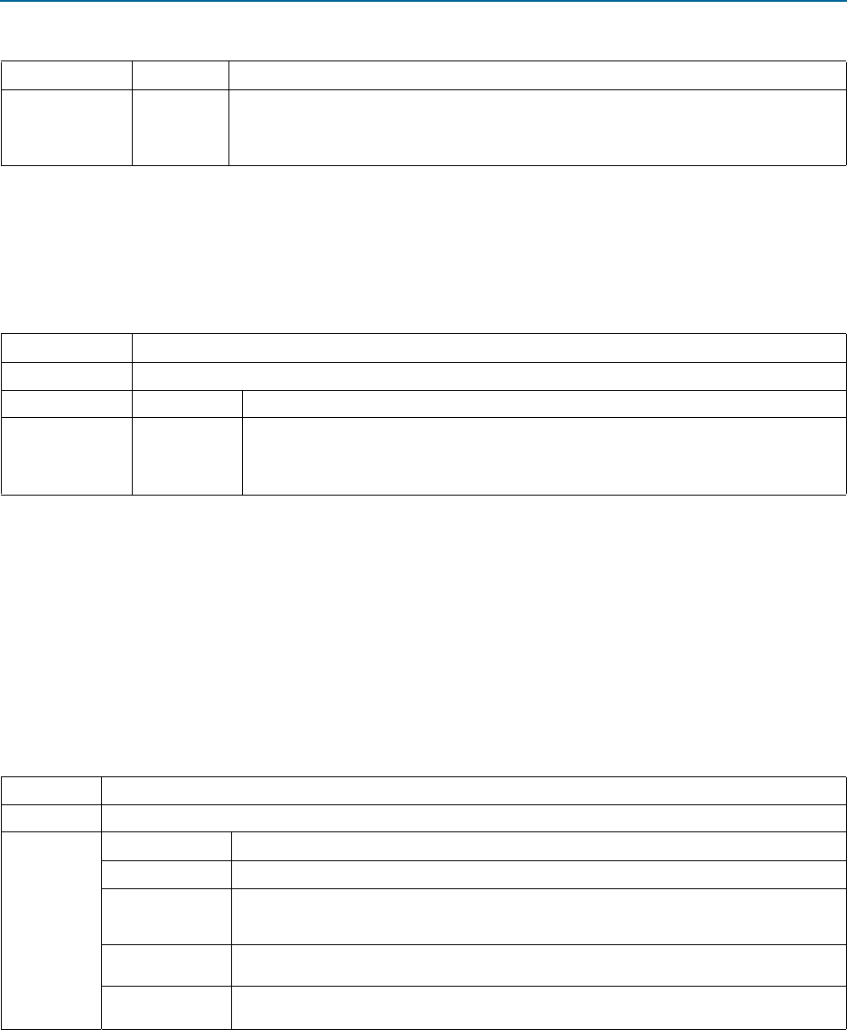
Table 17–55. chained_dma_test Procedure
Location altpcietb_bfm_driver_rp.v
Syntax
chained_dma_test (bar_table, bar_num, direction, use_msi, use_eplast)
Arguments
bar_table
Address of the Endpoint
bar_table
structure in BFM shared memory.
bar_num
BAR number to analyze.
direction
When 0 the direction is read.
When 1 the direction is write.
Use_msi
When set, the Root Port uses native PCI Express MSI to detect the DMA completion.
Use_eplast
When set, the Root Port uses BFM shared memory polling to detect the DMA completion.