
User guide

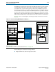
Table Of Contents
- Cyclone V Hard IP for PCI Express User Guide
- Contents
- 1. Datasheet
- 2. Getting Started with the Cyclone V Hard IP for PCI Express
- 3. Getting Started with the Avalon-MM Cyclone Hard IP for PCI Express
- Running Qsys
- Customizing the Cyclone VHard IP for PCI Express IP Core
- Adding the Remaining Components to the Qsys System
- Completing the Connections in Qsys
- Specifying Clocks and Interrupts
- Specifying Exported Interfaces
- Specifying Address Assignments
- Simulating the Example Design
- Simulating the Single DWord Design
- Understanding Channel Placement Guidelines
- Adding Synopsis Design Constraints
- Creating a Quartus II Project
- Compiling the Design
- Programming a Device
- 4. Parameter Settings for the Cyclone V Hard IP for PCI Express
- 5. Parameter Settings for the Avalon-MM Cyclone V Hard IP for PCI Express
- 6. IP Core Architecture
- Key Interfaces
- Protocol Layers
- Multi-Function Support
- PCI Express Avalon-MM Bridge
- Avalon-MM Bridge TLPs
- Avalon-MM-to-PCI Express Write Requests
- Avalon-MM-to-PCI Express Upstream Read Requests
- PCI Express-to-Avalon-MM Read Completions
- PCI Express-to-Avalon-MM Downstream Write Requests
- PCI Express-to-Avalon-MM Downstream Read Requests
- Avalon-MM-to-PCI Express Read Completions
- PCI Express-to-Avalon-MM Address Translation for Endpoints
- Minimizing BAR Sizes and the PCIe Address Space
- Avalon-MM-to-PCI Express Address Translation Algorithm
- Single DWord Completer Endpoint
- 7. IP Core Interfaces
- Cyclone V Hard IP for PCI Express
- Avalon-MM Hard IP for PCI Express
- Physical Layer Interface Signals
- Test Signals
- 8. Register Descriptions
- Configuration Space Register Content
- Altera-Defined Vendor Specific Extended Capability (VSEC)
- PCI Express Avalon-MM Bridge Control Register Access Content
- Avalon-MM to PCI Express Interrupt Registers
- PCI Express Mailbox Registers
- Avalon-MM-to-PCI Express Address Translation Table
- Root Port TLP Data Registers
- Programming Model for Avalon-MM Root Port
- PCI Express to Avalon-MM Interrupt Status and Enable Registers for Root Ports
- PCI Express to Avalon-MM Interrupt Status and Enable Registers for Endpoints
- Avalon-MM Mailbox Registers
- Correspondence between Configuration Space Registers and the PCIe Spec 2.1
- 9. Reset and Clocks
- 10. Transaction Layer Protocol (TLP) Details
- 11. Interrupts
- Interrupts for Endpoints Using the Avalon-ST Application Interface
- Interrupts for Root Ports Using the Avalon-ST Interface to the Application Layer
- Interrupts for Endpoints Using the Avalon-MM Interface to the Application Layer
- Interrupts for End Points Using the Avalon-MM Interface with Multiple MSI/MSI-X Support
- 12. Optional Features
- 13. Flow Control
- 14. Error Handling
- 15. Transceiver PHY IP Reconfiguration
- 16. SDC Timing Constraints
- 17. Testbench and Design Example
- Endpoint Testbench
- Root Port Testbench
- Chaining DMA Design Examples
- Test Driver Module
- Root Port Design Example
- Root Port BFM
- BFM Procedures and Functions
- 18. Debugging
- A. Transaction Layer Packet (TLP) Header Formats
- Additional Information
December 2013 Altera Corporation Cyclone V Hard IP for PCI Express
User Guide
16. SDC Timing Constraints
You must include component-level Synopsys Design Constraints (SDC) timing
constraints for the Cyclone V Hard IP for PCI Express IP Core and system-level
constraints for your complete design. The example design that Altera describes in the
Testbench and Design Example chapter includes the constraints required for the for
Cyclone V Hard IP for PCI Express IP Core and example design. A single file,
<install_dir>/ip/altera/altera_pcie/
altera_pcie_hip_ast_ed/altpcied_sv.sdc, includes both the component-level and
system-level constraints. Example 16–1 shows altpcied_sv.sdc. This .sdc file includes
constraints for three components:
■ Cyclone V Hard IP for PCI Express IP Core
■ Transceiver Reconfiguration Controller IP Core
■ Transceiver PHY Reset Controller IP Core
SDC Constraints for the Hard IP for PCIe
In Example 16–1, you should only apply the first two constraints, to derive PLL clocks
and clock uncertainty, once across all of the SDC files in your project. Differences
between Fitter timing analysis and TimeQuest timing analysis arise if these
constraints are applied more than once.
Example 16–1. SDC Timing Constraints Required for the Cyclone V Hard IP for PCIe and Design Example
# Constraints required for the Hard IP for PCI Express
# derive_pll_clock is used to calculate all clock derived from PCIe refclk
# the derive_pll_clocks and derive clock_uncertainty should only be applied
# once across all of the SDC files used in a project
derive_pll_clocks -create_base_clocks
derive_clock_uncertainty
##############################################################################
# PHY IP reconfig controller constraints
# Set reconfig_xcvr clock
# this line will likely need to be modified to match the actual clock pin name
# used for this clock, and also changed to have the correct period set for the actually
used clock
create_clock -period "125 MHz" -name {reconfig_xcvr_clk} {*reconfig_xcvr_clk*}
set_false_path -from
######################################################################
# HIP Soft reset controller SDC constraints
set_false_path -to [get_registers *altpcie_rs_serdes|fifo_err_sync_r[0]]
set_false_path -from [get_registers *sv_xcvr_pipe_native*] -to [get_registers
*altpcie_rs_serdes|*]