
User guide
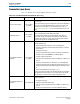
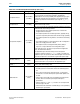


Table Of Contents
- Cyclone V Hard IP for PCI Express User Guide
- Contents
- 1. Datasheet
- 2. Getting Started with the Cyclone V Hard IP for PCI Express
- 3. Getting Started with the Avalon-MM Cyclone Hard IP for PCI Express
- Running Qsys
- Customizing the Cyclone VHard IP for PCI Express IP Core
- Adding the Remaining Components to the Qsys System
- Completing the Connections in Qsys
- Specifying Clocks and Interrupts
- Specifying Exported Interfaces
- Specifying Address Assignments
- Simulating the Example Design
- Simulating the Single DWord Design
- Understanding Channel Placement Guidelines
- Adding Synopsis Design Constraints
- Creating a Quartus II Project
- Compiling the Design
- Programming a Device
- 4. Parameter Settings for the Cyclone V Hard IP for PCI Express
- 5. Parameter Settings for the Avalon-MM Cyclone V Hard IP for PCI Express
- 6. IP Core Architecture
- Key Interfaces
- Protocol Layers
- Multi-Function Support
- PCI Express Avalon-MM Bridge
- Avalon-MM Bridge TLPs
- Avalon-MM-to-PCI Express Write Requests
- Avalon-MM-to-PCI Express Upstream Read Requests
- PCI Express-to-Avalon-MM Read Completions
- PCI Express-to-Avalon-MM Downstream Write Requests
- PCI Express-to-Avalon-MM Downstream Read Requests
- Avalon-MM-to-PCI Express Read Completions
- PCI Express-to-Avalon-MM Address Translation for Endpoints
- Minimizing BAR Sizes and the PCIe Address Space
- Avalon-MM-to-PCI Express Address Translation Algorithm
- Single DWord Completer Endpoint
- 7. IP Core Interfaces
- Cyclone V Hard IP for PCI Express
- Avalon-MM Hard IP for PCI Express
- Physical Layer Interface Signals
- Test Signals
- 8. Register Descriptions
- Configuration Space Register Content
- Altera-Defined Vendor Specific Extended Capability (VSEC)
- PCI Express Avalon-MM Bridge Control Register Access Content
- Avalon-MM to PCI Express Interrupt Registers
- PCI Express Mailbox Registers
- Avalon-MM-to-PCI Express Address Translation Table
- Root Port TLP Data Registers
- Programming Model for Avalon-MM Root Port
- PCI Express to Avalon-MM Interrupt Status and Enable Registers for Root Ports
- PCI Express to Avalon-MM Interrupt Status and Enable Registers for Endpoints
- Avalon-MM Mailbox Registers
- Correspondence between Configuration Space Registers and the PCIe Spec 2.1
- 9. Reset and Clocks
- 10. Transaction Layer Protocol (TLP) Details
- 11. Interrupts
- Interrupts for Endpoints Using the Avalon-ST Application Interface
- Interrupts for Root Ports Using the Avalon-ST Interface to the Application Layer
- Interrupts for Endpoints Using the Avalon-MM Interface to the Application Layer
- Interrupts for End Points Using the Avalon-MM Interface with Multiple MSI/MSI-X Support
- 12. Optional Features
- 13. Flow Control
- 14. Error Handling
- 15. Transceiver PHY IP Reconfiguration
- 16. SDC Timing Constraints
- 17. Testbench and Design Example
- Endpoint Testbench
- Root Port Testbench
- Chaining DMA Design Examples
- Test Driver Module
- Root Port Design Example
- Root Port BFM
- BFM Procedures and Functions
- 18. Debugging
- A. Transaction Layer Packet (TLP) Header Formats
- Additional Information
14–6 Chapter 14: Error Handling
Uncorrectable and Correctable Error Status Bits
Cyclone V Hard IP for PCI Express December 2013 Altera Corporation
User Guide
Uncorrectable and Correctable Error Status Bits
The following section is reprinted with the permission of PCI-SIG. Copyright 2010
PCI-SIGR.
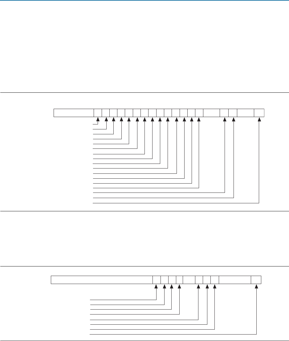
Figure 14–1 illustrates the Uncorrectable Error Status register. The default value of all
the bits of this register is 0. An error status bit that is set indicates that the error
condition it represents has been detected. Software may clear the error status by
writing a 1 to the appropriate bit.
Figure 14–2 illustrates the Correctable Error Status register. The default value of all the
bits of this register is 0. An error status bit that is set indicates that the error condition
it represents has been detected. Software may clear the error status by writing a 1 to
the appropriate bit.0
Figure 14–1. Uncorrectable Error Status Register
RsvdRsvdRsvd
TLP Prefix Blocked Error Status
AtomicOp Egress Blocked Status
MC Blocked TLP Status
Uncorrectable Internal Error Status
ACS Violation Status
Unsupported Request Error Status
ECRC Error Status
Malformed TLP Status
Receiver Overflow Status
Unexpected Completion Status
Completer Abort Status
Completion Timeout Status
Flow Control Protocol Status
Poisoned TLP Status
Surprise Down Error Status
Data Link Protocol Error Status
Undefined
22 21 20 1926 25 24 23 18 17 16 15 14 13 12 11 6 5 4 3 1031
Figure 14–2. Correctable Error Status Register
RsvdRsvdRsvd
Header Log Overflow Status
Corrected Internal Error Status
Advisory Non-Fatal Error Status
Replay Timer Timeout Status
REPLAY_NUM Rollover Status
Bad DLLP Status
Bad TLP Status
Receiver Error Status
16 15 14 13 12 11 9 8 7 6 5 1031