
User guide
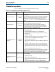
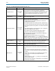
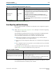

Table Of Contents
- Cyclone V Hard IP for PCI Express User Guide
- Contents
- 1. Datasheet
- 2. Getting Started with the Cyclone V Hard IP for PCI Express
- 3. Getting Started with the Avalon-MM Cyclone Hard IP for PCI Express
- Running Qsys
- Customizing the Cyclone VHard IP for PCI Express IP Core
- Adding the Remaining Components to the Qsys System
- Completing the Connections in Qsys
- Specifying Clocks and Interrupts
- Specifying Exported Interfaces
- Specifying Address Assignments
- Simulating the Example Design
- Simulating the Single DWord Design
- Understanding Channel Placement Guidelines
- Adding Synopsis Design Constraints
- Creating a Quartus II Project
- Compiling the Design
- Programming a Device
- 4. Parameter Settings for the Cyclone V Hard IP for PCI Express
- 5. Parameter Settings for the Avalon-MM Cyclone V Hard IP for PCI Express
- 6. IP Core Architecture
- Key Interfaces
- Protocol Layers
- Multi-Function Support
- PCI Express Avalon-MM Bridge
- Avalon-MM Bridge TLPs
- Avalon-MM-to-PCI Express Write Requests
- Avalon-MM-to-PCI Express Upstream Read Requests
- PCI Express-to-Avalon-MM Read Completions
- PCI Express-to-Avalon-MM Downstream Write Requests
- PCI Express-to-Avalon-MM Downstream Read Requests
- Avalon-MM-to-PCI Express Read Completions
- PCI Express-to-Avalon-MM Address Translation for Endpoints
- Minimizing BAR Sizes and the PCIe Address Space
- Avalon-MM-to-PCI Express Address Translation Algorithm
- Single DWord Completer Endpoint
- 7. IP Core Interfaces
- Cyclone V Hard IP for PCI Express
- Avalon-MM Hard IP for PCI Express
- Physical Layer Interface Signals
- Test Signals
- 8. Register Descriptions
- Configuration Space Register Content
- Altera-Defined Vendor Specific Extended Capability (VSEC)
- PCI Express Avalon-MM Bridge Control Register Access Content
- Avalon-MM to PCI Express Interrupt Registers
- PCI Express Mailbox Registers
- Avalon-MM-to-PCI Express Address Translation Table
- Root Port TLP Data Registers
- Programming Model for Avalon-MM Root Port
- PCI Express to Avalon-MM Interrupt Status and Enable Registers for Root Ports
- PCI Express to Avalon-MM Interrupt Status and Enable Registers for Endpoints
- Avalon-MM Mailbox Registers
- Correspondence between Configuration Space Registers and the PCIe Spec 2.1
- 9. Reset and Clocks
- 10. Transaction Layer Protocol (TLP) Details
- 11. Interrupts
- Interrupts for Endpoints Using the Avalon-ST Application Interface
- Interrupts for Root Ports Using the Avalon-ST Interface to the Application Layer
- Interrupts for Endpoints Using the Avalon-MM Interface to the Application Layer
- Interrupts for End Points Using the Avalon-MM Interface with Multiple MSI/MSI-X Support
- 12. Optional Features
- 13. Flow Control
- 14. Error Handling
- 15. Transceiver PHY IP Reconfiguration
- 16. SDC Timing Constraints
- 17. Testbench and Design Example
- Endpoint Testbench
- Root Port Testbench
- Chaining DMA Design Examples
- Test Driver Module
- Root Port Design Example
- Root Port BFM
- BFM Procedures and Functions
- 18. Debugging
- A. Transaction Layer Packet (TLP) Header Formats
- Additional Information

Chapter 14: Error Handling 14–5
Error Reporting and Data Poisoning
December 2013 Altera Corporation Cyclone V Hard IP for PCI Express
User Guide
Error Reporting and Data Poisoning
How the Endpoint handles a particular error depends on the configuration registers
of the device.
f Refer to the PCI Express Base Specification 2.1 for a description of the device signaling
and logging for an Endpoint.
The Hard IP block implements data poisoning, a mechanism for indicating that the
data associated with a transaction is corrupted. Poisoned TLPs have the
error/poisoned bit of the header set to 1 and observe the following rules:
■ Received poisoned TLPs are sent to the Application Layer and status bits are
automatically updated in the Configuration Space.
■ Received poisoned Configuration Write TLPs are not written in the Configuration
Space.
■ The Configuration Space never generates a poisoned TLP; the error/poisoned bit
of the header is always set to 0.
Poisoned TLPs can also set the parity error bits in the PCI Configuration Space Status
register. Table 14–5 lists the conditions that cause parity errors.
Poisoned packets received by the Hard IP block are passed to the Application Layer.
Poisoned transmit TLPs are similarly sent to the link.
Malformed TLP
(continued)
Uncorrectable
(fatal)
■ A request specifies an address/length combination that causes a
memory space access to exceed a 4 KByte boundary. The Hard IP
block checks for this violation, which is considered optional by the
PCI Express specification.
■ Messages, such as Assert_INTX, Power Management, Error
Signaling, Unlock, and Set Power Slot Limit, must be transmitted
across the default traffic class.
The Hard IP block deletes the malformed TLP; it is not presented to the
Application Layer.
Note to Table 14–4:
(1) Considered optional by the PCI Express Base Specification Revision 2.1.
Table 14–4. Errors Detected by the Transaction Layer (Part 3 of 3)
Error Type Description
Table 14–5. Parity Error Conditions
Status Bit Conditions
Detected parity error (status register bit 15) Set when any received TLP is poisoned.
Master data parity error (status register bit 8)
This bit is set when the command register parity enable bit is set and one of
the following conditions is true:
■ The poisoned bit is set during the transmission of a Write Request TLP.
■ The poisoned bit is set on a received completion TLP.