
User guide
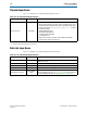
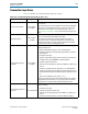
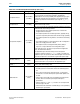
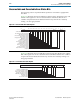

Table Of Contents
- Cyclone V Hard IP for PCI Express User Guide
- Contents
- 1. Datasheet
- 2. Getting Started with the Cyclone V Hard IP for PCI Express
- 3. Getting Started with the Avalon-MM Cyclone Hard IP for PCI Express
- Running Qsys
- Customizing the Cyclone VHard IP for PCI Express IP Core
- Adding the Remaining Components to the Qsys System
- Completing the Connections in Qsys
- Specifying Clocks and Interrupts
- Specifying Exported Interfaces
- Specifying Address Assignments
- Simulating the Example Design
- Simulating the Single DWord Design
- Understanding Channel Placement Guidelines
- Adding Synopsis Design Constraints
- Creating a Quartus II Project
- Compiling the Design
- Programming a Device
- 4. Parameter Settings for the Cyclone V Hard IP for PCI Express
- 5. Parameter Settings for the Avalon-MM Cyclone V Hard IP for PCI Express
- 6. IP Core Architecture
- Key Interfaces
- Protocol Layers
- Multi-Function Support
- PCI Express Avalon-MM Bridge
- Avalon-MM Bridge TLPs
- Avalon-MM-to-PCI Express Write Requests
- Avalon-MM-to-PCI Express Upstream Read Requests
- PCI Express-to-Avalon-MM Read Completions
- PCI Express-to-Avalon-MM Downstream Write Requests
- PCI Express-to-Avalon-MM Downstream Read Requests
- Avalon-MM-to-PCI Express Read Completions
- PCI Express-to-Avalon-MM Address Translation for Endpoints
- Minimizing BAR Sizes and the PCIe Address Space
- Avalon-MM-to-PCI Express Address Translation Algorithm
- Single DWord Completer Endpoint
- 7. IP Core Interfaces
- Cyclone V Hard IP for PCI Express
- Avalon-MM Hard IP for PCI Express
- Physical Layer Interface Signals
- Test Signals
- 8. Register Descriptions
- Configuration Space Register Content
- Altera-Defined Vendor Specific Extended Capability (VSEC)
- PCI Express Avalon-MM Bridge Control Register Access Content
- Avalon-MM to PCI Express Interrupt Registers
- PCI Express Mailbox Registers
- Avalon-MM-to-PCI Express Address Translation Table
- Root Port TLP Data Registers
- Programming Model for Avalon-MM Root Port
- PCI Express to Avalon-MM Interrupt Status and Enable Registers for Root Ports
- PCI Express to Avalon-MM Interrupt Status and Enable Registers for Endpoints
- Avalon-MM Mailbox Registers
- Correspondence between Configuration Space Registers and the PCIe Spec 2.1
- 9. Reset and Clocks
- 10. Transaction Layer Protocol (TLP) Details
- 11. Interrupts
- Interrupts for Endpoints Using the Avalon-ST Application Interface
- Interrupts for Root Ports Using the Avalon-ST Interface to the Application Layer
- Interrupts for Endpoints Using the Avalon-MM Interface to the Application Layer
- Interrupts for End Points Using the Avalon-MM Interface with Multiple MSI/MSI-X Support
- 12. Optional Features
- 13. Flow Control
- 14. Error Handling
- 15. Transceiver PHY IP Reconfiguration
- 16. SDC Timing Constraints
- 17. Testbench and Design Example
- Endpoint Testbench
- Root Port Testbench
- Chaining DMA Design Examples
- Test Driver Module
- Root Port Design Example
- Root Port BFM
- BFM Procedures and Functions
- 18. Debugging
- A. Transaction Layer Packet (TLP) Header Formats
- Additional Information

14–2 Chapter 14: Error Handling
Physical Layer Errors
Cyclone V Hard IP for PCI Express December 2013 Altera Corporation
User Guide
Physical Layer Errors
Table 14–2 describes errors detected by the Physical Layer.
P
Data Link Layer Errors
Table 14–3 describes errors detected by the Data Link Layer.
Table 14–2. Errors Detected by the Physical Layer
(1)
Error Type Description
Receive port error Correctable
This error has the following 3 potential causes:
■ Physical coding sublayer error when a lane is in L0 state. These errors
are reported to the Hard IP block via the per lane PIPE interface input
receive status signals,
rxstatus
<lane_number>
[2:0]
using the
following encodings:
100: 8B/10B Decode Error
101: Elastic Buffer Overflow
110: Elastic Buffer Underflow
111: Disparity Error
■ Deskew error caused by overflow of the multilane deskew FIFO.
■ Control symbol received in wrong lane.
Note to Table 14–2:
(1) Considered optional by the PCI Express specification.
Table 14–3. Errors Detected by the Data Link Layer
Error Type Description
Bad TLP Correctable
This error occurs when a LCRC verification fails or when a sequence
number error occurs.
Bad DLLP Correctable This error occurs when a CRC verification fails.
Replay timer Correctable This error occurs when the replay timer times out.
Replay num rollover Correctable This error occurs when the replay number rolls over.
Data Link Layer protocol
Uncorrectable
(fatal)
This error occurs when a sequence number specified by the Ack/Nak
block in the Data Link Layer (
AckNak_Seq_Num)
does not correspond to
an unacknowledged TLP. (Refer to “Data Link Layer” on page 6–8.)