
User guide

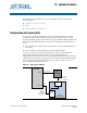
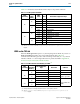

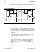

Table Of Contents
- Cyclone V Hard IP for PCI Express User Guide
- Contents
- 1. Datasheet
- 2. Getting Started with the Cyclone V Hard IP for PCI Express
- 3. Getting Started with the Avalon-MM Cyclone Hard IP for PCI Express
- Running Qsys
- Customizing the Cyclone VHard IP for PCI Express IP Core
- Adding the Remaining Components to the Qsys System
- Completing the Connections in Qsys
- Specifying Clocks and Interrupts
- Specifying Exported Interfaces
- Specifying Address Assignments
- Simulating the Example Design
- Simulating the Single DWord Design
- Understanding Channel Placement Guidelines
- Adding Synopsis Design Constraints
- Creating a Quartus II Project
- Compiling the Design
- Programming a Device
- 4. Parameter Settings for the Cyclone V Hard IP for PCI Express
- 5. Parameter Settings for the Avalon-MM Cyclone V Hard IP for PCI Express
- 6. IP Core Architecture
- Key Interfaces
- Protocol Layers
- Multi-Function Support
- PCI Express Avalon-MM Bridge
- Avalon-MM Bridge TLPs
- Avalon-MM-to-PCI Express Write Requests
- Avalon-MM-to-PCI Express Upstream Read Requests
- PCI Express-to-Avalon-MM Read Completions
- PCI Express-to-Avalon-MM Downstream Write Requests
- PCI Express-to-Avalon-MM Downstream Read Requests
- Avalon-MM-to-PCI Express Read Completions
- PCI Express-to-Avalon-MM Address Translation for Endpoints
- Minimizing BAR Sizes and the PCIe Address Space
- Avalon-MM-to-PCI Express Address Translation Algorithm
- Single DWord Completer Endpoint
- 7. IP Core Interfaces
- Cyclone V Hard IP for PCI Express
- Avalon-MM Hard IP for PCI Express
- Physical Layer Interface Signals
- Test Signals
- 8. Register Descriptions
- Configuration Space Register Content
- Altera-Defined Vendor Specific Extended Capability (VSEC)
- PCI Express Avalon-MM Bridge Control Register Access Content
- Avalon-MM to PCI Express Interrupt Registers
- PCI Express Mailbox Registers
- Avalon-MM-to-PCI Express Address Translation Table
- Root Port TLP Data Registers
- Programming Model for Avalon-MM Root Port
- PCI Express to Avalon-MM Interrupt Status and Enable Registers for Root Ports
- PCI Express to Avalon-MM Interrupt Status and Enable Registers for Endpoints
- Avalon-MM Mailbox Registers
- Correspondence between Configuration Space Registers and the PCIe Spec 2.1
- 9. Reset and Clocks
- 10. Transaction Layer Protocol (TLP) Details
- 11. Interrupts
- Interrupts for Endpoints Using the Avalon-ST Application Interface
- Interrupts for Root Ports Using the Avalon-ST Interface to the Application Layer
- Interrupts for Endpoints Using the Avalon-MM Interface to the Application Layer
- Interrupts for End Points Using the Avalon-MM Interface with Multiple MSI/MSI-X Support
- 12. Optional Features
- 13. Flow Control
- 14. Error Handling
- 15. Transceiver PHY IP Reconfiguration
- 16. SDC Timing Constraints
- 17. Testbench and Design Example
- Endpoint Testbench
- Root Port Testbench
- Chaining DMA Design Examples
- Test Driver Module
- Root Port Design Example
- Root Port BFM
- BFM Procedures and Functions
- 18. Debugging
- A. Transaction Layer Packet (TLP) Header Formats
- Additional Information

December 2013 Altera Corporation Cyclone V Hard IP for PCI Express
User Guide
13. Flow Control
Throughput analysis requires that you understand the Flow Control Loop, shown in
“Flow Control Update Loop” on page 13–2. This chapter discusses the Flow Control
Loop and strategies to improve throughput. It covers the following topics:
■ Throughput of Posted Writes
■ Throughput of Non-Posted Reads
Throughput of Posted Writes
The throughput of posted writes is limited primarily by the Flow Control Update loop
shown in Figure 13–1. If the write requester sources the data as quickly as possible,
and the completer consumes the data as quickly as possible, then the Flow Control
Update loop may be the biggest determining factor in write throughput, after the
actual bandwidth of the link.
Figure 13–1 shows the main components of the Flow Control Update loop with two
communicating PCI Express ports:
■ Write Requester
■ Write Completer
As the PCI Express Base Specification 2.1 describes, each transmitter, the write requester
in this case, maintains a
Credit
Limit
Register
and a
Credits
Consumed
Register
.
The
Credit
Limit
Register
is the sum of all credits issued by the receiver, the write
completer in this case. The
Credit
Limit
Register
is initialized during the flow
control initialization phase of link initialization and then updated during operation by
Flow Control (FC) Update DLLPs. The
Credits
Consumed
Register
is the sum of all
credits consumed by packets transmitted. Separate
Credit
Limit
and
Credits
Consumed
Registers
exist for each of the six types of Flow Control:
■ Posted Headers
■ Posted Data
■ Non-Posted Headers
■ Non-Posted Data
■ Completion Headers
■ Completion Data
December 2013
UG-01110-1.5