
User guide
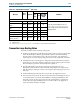
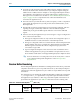

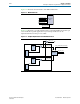

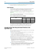
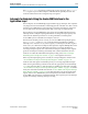
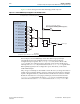
Table Of Contents
- Cyclone V Hard IP for PCI Express User Guide
- Contents
- 1. Datasheet
- 2. Getting Started with the Cyclone V Hard IP for PCI Express
- 3. Getting Started with the Avalon-MM Cyclone Hard IP for PCI Express
- Running Qsys
- Customizing the Cyclone VHard IP for PCI Express IP Core
- Adding the Remaining Components to the Qsys System
- Completing the Connections in Qsys
- Specifying Clocks and Interrupts
- Specifying Exported Interfaces
- Specifying Address Assignments
- Simulating the Example Design
- Simulating the Single DWord Design
- Understanding Channel Placement Guidelines
- Adding Synopsis Design Constraints
- Creating a Quartus II Project
- Compiling the Design
- Programming a Device
- 4. Parameter Settings for the Cyclone V Hard IP for PCI Express
- 5. Parameter Settings for the Avalon-MM Cyclone V Hard IP for PCI Express
- 6. IP Core Architecture
- Key Interfaces
- Protocol Layers
- Multi-Function Support
- PCI Express Avalon-MM Bridge
- Avalon-MM Bridge TLPs
- Avalon-MM-to-PCI Express Write Requests
- Avalon-MM-to-PCI Express Upstream Read Requests
- PCI Express-to-Avalon-MM Read Completions
- PCI Express-to-Avalon-MM Downstream Write Requests
- PCI Express-to-Avalon-MM Downstream Read Requests
- Avalon-MM-to-PCI Express Read Completions
- PCI Express-to-Avalon-MM Address Translation for Endpoints
- Minimizing BAR Sizes and the PCIe Address Space
- Avalon-MM-to-PCI Express Address Translation Algorithm
- Single DWord Completer Endpoint
- 7. IP Core Interfaces
- Cyclone V Hard IP for PCI Express
- Avalon-MM Hard IP for PCI Express
- Physical Layer Interface Signals
- Test Signals
- 8. Register Descriptions
- Configuration Space Register Content
- Altera-Defined Vendor Specific Extended Capability (VSEC)
- PCI Express Avalon-MM Bridge Control Register Access Content
- Avalon-MM to PCI Express Interrupt Registers
- PCI Express Mailbox Registers
- Avalon-MM-to-PCI Express Address Translation Table
- Root Port TLP Data Registers
- Programming Model for Avalon-MM Root Port
- PCI Express to Avalon-MM Interrupt Status and Enable Registers for Root Ports
- PCI Express to Avalon-MM Interrupt Status and Enable Registers for Endpoints
- Avalon-MM Mailbox Registers
- Correspondence between Configuration Space Registers and the PCIe Spec 2.1
- 9. Reset and Clocks
- 10. Transaction Layer Protocol (TLP) Details
- 11. Interrupts
- Interrupts for Endpoints Using the Avalon-ST Application Interface
- Interrupts for Root Ports Using the Avalon-ST Interface to the Application Layer
- Interrupts for Endpoints Using the Avalon-MM Interface to the Application Layer
- Interrupts for End Points Using the Avalon-MM Interface with Multiple MSI/MSI-X Support
- 12. Optional Features
- 13. Flow Control
- 14. Error Handling
- 15. Transceiver PHY IP Reconfiguration
- 16. SDC Timing Constraints
- 17. Testbench and Design Example
- Endpoint Testbench
- Root Port Testbench
- Chaining DMA Design Examples
- Test Driver Module
- Root Port Design Example
- Root Port BFM
- BFM Procedures and Functions
- 18. Debugging
- A. Transaction Layer Packet (TLP) Header Formats
- Additional Information
11–4 Chapter 11: Interrupts
Interrupts for Root Ports Using the Avalon-ST Interface to the Application Layer
Cyclone V Hard IP for PCI Express December 2013 Altera Corporation
User Guide
f For more information about implementing the MSI-X capability structure, refer
Section 6.8.2. of the PCI Local Bus Specification, Revision 3.0.
Legacy Interrupts
Legacy interrupts are signaled on the PCI Express link using message TLPs that are
generated internally by the Cyclone V Hard IP for PCI Express IP core. The
tl
_
app_int_sts_vec
input port controls interrupt generation. To use legacy
interrupts, you must clear the
Interrupt Disable
bit, which is bit 10 of the
Command
register (Table 8–2 on page 8–2). Then, turn off the
MSI Enable
bit (Table 7–15 on
page 7–37.)
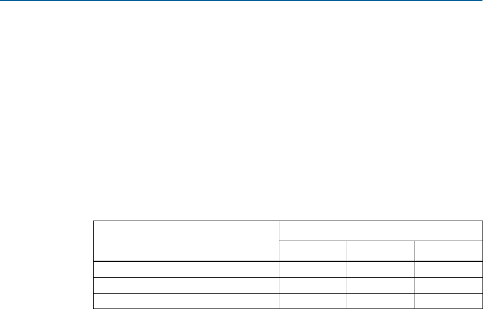
Table 11–1 describes 3 example implementations; 1 in which all 32 MSI messages are
allocated and 2 in which only 4 are allocated.
MSI interrupts generated for Hot Plug, Power Management Events, and System
Errors always use TC0. MSI interrupts generated by the Application Layer can use
any Traffic Class. For example, a DMA that generates an MSI at the end of a
transmission can use the same traffic control as was used to transfer data.
Interrupts for Root Ports Using the Avalon-ST Interface to the
Application Layer
In Root Port mode, the Cyclone V Hard IP for PCI Express IP core receives interrupts
through two different mechanisms:
■ MSI—Root Ports receive MSI interrupts through the Avalon-ST RX TLP of type
MWr
. This is a memory mapped mechanism.
■ Legacy—Legacy interrupts are translated into TLPs of type
Message
Interrupt
which is sent to the Application Layer using the
int_status[3:0]
pins.
Normally, the Root Port services rather than sends interrupts; however, in two
circumstances the Root Port can send an interrupt to itself to record error conditions:
■ When the AER option is enabled, the
aer_msi_num[4:0]
signal indicates which
MSI is being sent to the root complex when an error is logged in the AER
Capability structure. This mechanism is an alternative to using the
serr_out
signal. The
aer_msi_num[4:0]
is only used for Root Ports and you must set it to a
constant value. It cannot toggle during operation.
■ If the Root Port detects a Power Management Event, the
pex_msi_num[4:0]
signal
is used by Power Management or Hot Plug to determine the offset between the
base message interrupt number and the message interrupt number to send
through MSI. The user must set
pex_msi_num[4:0]
to a fixed value.
Table 11–1. MSI Messages Requested, Allocated, and Mapped
MSI
Allocated
32 4 4
System error 31 3 3
Hot plug and power management event 30 2 3
Application Layer 29:0 1:0 2:0