
User guide
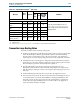
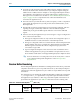

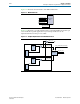

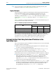
Table Of Contents
- Cyclone V Hard IP for PCI Express User Guide
- Contents
- 1. Datasheet
- 2. Getting Started with the Cyclone V Hard IP for PCI Express
- 3. Getting Started with the Avalon-MM Cyclone Hard IP for PCI Express
- Running Qsys
- Customizing the Cyclone VHard IP for PCI Express IP Core
- Adding the Remaining Components to the Qsys System
- Completing the Connections in Qsys
- Specifying Clocks and Interrupts
- Specifying Exported Interfaces
- Specifying Address Assignments
- Simulating the Example Design
- Simulating the Single DWord Design
- Understanding Channel Placement Guidelines
- Adding Synopsis Design Constraints
- Creating a Quartus II Project
- Compiling the Design
- Programming a Device
- 4. Parameter Settings for the Cyclone V Hard IP for PCI Express
- 5. Parameter Settings for the Avalon-MM Cyclone V Hard IP for PCI Express
- 6. IP Core Architecture
- Key Interfaces
- Protocol Layers
- Multi-Function Support
- PCI Express Avalon-MM Bridge
- Avalon-MM Bridge TLPs
- Avalon-MM-to-PCI Express Write Requests
- Avalon-MM-to-PCI Express Upstream Read Requests
- PCI Express-to-Avalon-MM Read Completions
- PCI Express-to-Avalon-MM Downstream Write Requests
- PCI Express-to-Avalon-MM Downstream Read Requests
- Avalon-MM-to-PCI Express Read Completions
- PCI Express-to-Avalon-MM Address Translation for Endpoints
- Minimizing BAR Sizes and the PCIe Address Space
- Avalon-MM-to-PCI Express Address Translation Algorithm
- Single DWord Completer Endpoint
- 7. IP Core Interfaces
- Cyclone V Hard IP for PCI Express
- Avalon-MM Hard IP for PCI Express
- Physical Layer Interface Signals
- Test Signals
- 8. Register Descriptions
- Configuration Space Register Content
- Altera-Defined Vendor Specific Extended Capability (VSEC)
- PCI Express Avalon-MM Bridge Control Register Access Content
- Avalon-MM to PCI Express Interrupt Registers
- PCI Express Mailbox Registers
- Avalon-MM-to-PCI Express Address Translation Table
- Root Port TLP Data Registers
- Programming Model for Avalon-MM Root Port
- PCI Express to Avalon-MM Interrupt Status and Enable Registers for Root Ports
- PCI Express to Avalon-MM Interrupt Status and Enable Registers for Endpoints
- Avalon-MM Mailbox Registers
- Correspondence between Configuration Space Registers and the PCIe Spec 2.1
- 9. Reset and Clocks
- 10. Transaction Layer Protocol (TLP) Details
- 11. Interrupts
- Interrupts for Endpoints Using the Avalon-ST Application Interface
- Interrupts for Root Ports Using the Avalon-ST Interface to the Application Layer
- Interrupts for Endpoints Using the Avalon-MM Interface to the Application Layer
- Interrupts for End Points Using the Avalon-MM Interface with Multiple MSI/MSI-X Support
- 12. Optional Features
- 13. Flow Control
- 14. Error Handling
- 15. Transceiver PHY IP Reconfiguration
- 16. SDC Timing Constraints
- 17. Testbench and Design Example
- Endpoint Testbench
- Root Port Testbench
- Chaining DMA Design Examples
- Test Driver Module
- Root Port Design Example
- Root Port BFM
- BFM Procedures and Functions
- 18. Debugging
- A. Transaction Layer Packet (TLP) Header Formats
- Additional Information
Chapter 11: Interrupts 11–3
Interrupts for Endpoints Using the Avalon-ST Application Interface
December 2013 Altera Corporation Cyclone V Hard IP for PCI Express
User Guide
There are 32 possible MSI messages. The number of messages requested by a
particular component does not necessarily correspond to the number of messages
allocated. For example, in Figure 11–3, the Endpoint requests eight MSIs but is only
allocated two. In this case, you must design the Application Layer to use only two
allocated messages.
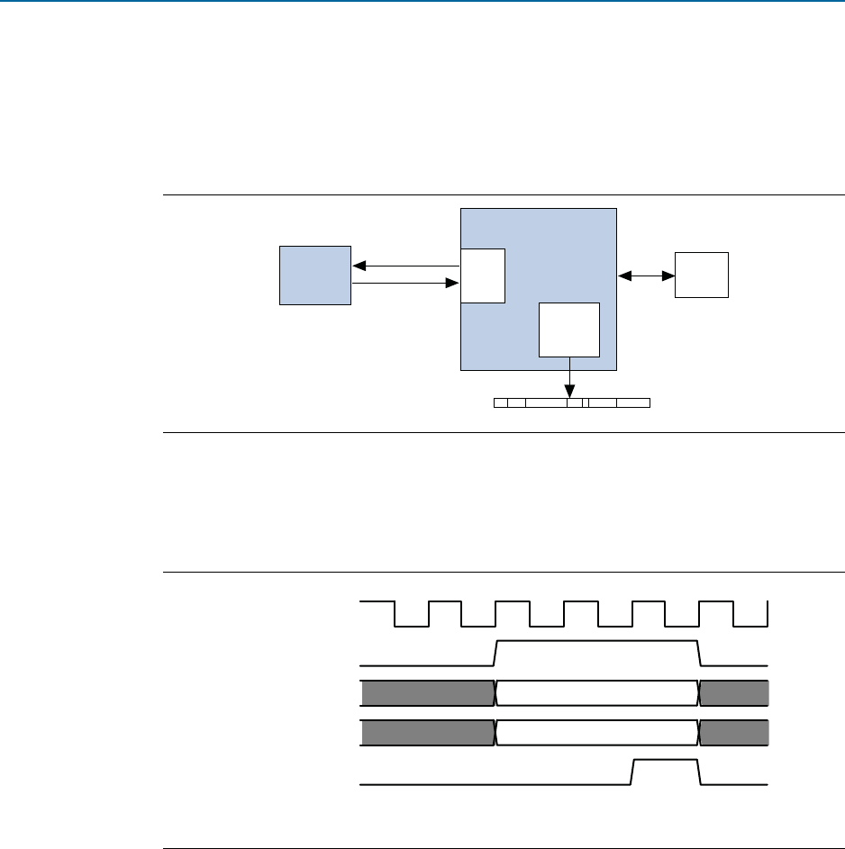
Figure 11–4 illustrates the interactions among MSI interrupt signals for the Root Port
in Figure 11–3. The minimum latency possible between
app_msi_req
and
app_msi_ack
is one clock cycle.
MSI-X
You can enable MSI-X interrupts by turning on Implement MSI-X on the MSI-X tab
under the PCI Express/PCI Capabilities heading using the parameter editor. If you
turn on the Implement MSI-X option, you should implement the MSI-X table
structures at the memory space pointed to by the BARs as part of your Application
Layer.
MSI-X TLPs are generated by the Application Layer and sent through the TX
interface. They are single dword memory writes so that
Last DW Byte Enable
in the
TLP header must be set to 4b’0000. MSI-X TLPs should be sent only when enabled by
the MSI-X enable and the function mask bits in the message control for MSI-X
Configuration register. These bits are available on the
tl_cfg_ctl
output bus.
Figure 11–3. MSI Request Example
Figure 11–4. MSI Interrupt Signals Waveform
(1)
Note to Figure 11–4:
(1)
app_msi_req
can extend beyond
app_msi_ack
before deasserting. F
Endpoint
8 Requested
2 Allocated
Root Complex
CPU
Interrupt Register
Root
Port
Interrupt
Block
coreclkout
app_msi_req
app_msi_tc[2:0]
app_msi_num[4:0]
app_msi_ack
123 56
4
valid
valid