
User guide
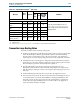
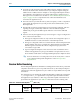


Table Of Contents
- Cyclone V Hard IP for PCI Express User Guide
- Contents
- 1. Datasheet
- 2. Getting Started with the Cyclone V Hard IP for PCI Express
- 3. Getting Started with the Avalon-MM Cyclone Hard IP for PCI Express
- Running Qsys
- Customizing the Cyclone VHard IP for PCI Express IP Core
- Adding the Remaining Components to the Qsys System
- Completing the Connections in Qsys
- Specifying Clocks and Interrupts
- Specifying Exported Interfaces
- Specifying Address Assignments
- Simulating the Example Design
- Simulating the Single DWord Design
- Understanding Channel Placement Guidelines
- Adding Synopsis Design Constraints
- Creating a Quartus II Project
- Compiling the Design
- Programming a Device
- 4. Parameter Settings for the Cyclone V Hard IP for PCI Express
- 5. Parameter Settings for the Avalon-MM Cyclone V Hard IP for PCI Express
- 6. IP Core Architecture
- Key Interfaces
- Protocol Layers
- Multi-Function Support
- PCI Express Avalon-MM Bridge
- Avalon-MM Bridge TLPs
- Avalon-MM-to-PCI Express Write Requests
- Avalon-MM-to-PCI Express Upstream Read Requests
- PCI Express-to-Avalon-MM Read Completions
- PCI Express-to-Avalon-MM Downstream Write Requests
- PCI Express-to-Avalon-MM Downstream Read Requests
- Avalon-MM-to-PCI Express Read Completions
- PCI Express-to-Avalon-MM Address Translation for Endpoints
- Minimizing BAR Sizes and the PCIe Address Space
- Avalon-MM-to-PCI Express Address Translation Algorithm
- Single DWord Completer Endpoint
- 7. IP Core Interfaces
- Cyclone V Hard IP for PCI Express
- Avalon-MM Hard IP for PCI Express
- Physical Layer Interface Signals
- Test Signals
- 8. Register Descriptions
- Configuration Space Register Content
- Altera-Defined Vendor Specific Extended Capability (VSEC)
- PCI Express Avalon-MM Bridge Control Register Access Content
- Avalon-MM to PCI Express Interrupt Registers
- PCI Express Mailbox Registers
- Avalon-MM-to-PCI Express Address Translation Table
- Root Port TLP Data Registers
- Programming Model for Avalon-MM Root Port
- PCI Express to Avalon-MM Interrupt Status and Enable Registers for Root Ports
- PCI Express to Avalon-MM Interrupt Status and Enable Registers for Endpoints
- Avalon-MM Mailbox Registers
- Correspondence between Configuration Space Registers and the PCIe Spec 2.1
- 9. Reset and Clocks
- 10. Transaction Layer Protocol (TLP) Details
- 11. Interrupts
- Interrupts for Endpoints Using the Avalon-ST Application Interface
- Interrupts for Root Ports Using the Avalon-ST Interface to the Application Layer
- Interrupts for Endpoints Using the Avalon-MM Interface to the Application Layer
- Interrupts for End Points Using the Avalon-MM Interface with Multiple MSI/MSI-X Support
- 12. Optional Features
- 13. Flow Control
- 14. Error Handling
- 15. Transceiver PHY IP Reconfiguration
- 16. SDC Timing Constraints
- 17. Testbench and Design Example
- Endpoint Testbench
- Root Port Testbench
- Chaining DMA Design Examples
- Test Driver Module
- Root Port Design Example
- Root Port BFM
- BFM Procedures and Functions
- 18. Debugging
- A. Transaction Layer Packet (TLP) Header Formats
- Additional Information

10–4 Chapter 10: Transaction Layer Protocol (TLP) Details
Receive Buffer Reordering
Cyclone V Hard IP for PCI Express December 2013 Altera Corporation
User Guide
■ For memory read and write request with addresses below 4 GBytes, requestors
must use the 32-bit format. The Transaction Layer interprets requests using the
64-bit format for addresses below 4 GBytes as an Unsupported Request and does
not send them to the Application Layer. If Error Messaging is enabled, an error
Message TLP is sent to the Root Port. Refer to “Errors Detected by the Transaction
Layer” on page 14–3 for a comprehensive list of TLPs the Hard IP does not
forward to the Application Layer.
■ The Transaction Layer sends all memory and I/O requests, as well as completions
generated by the Application Layer and passed to the transmit interface, to the
PCI Express link.
■ The Hard IP can generate and transmit power management, interrupt, and error
signaling messages automatically under the control of dedicated signals.
Additionally, it can generate MSI requests under the control of the dedicated
signals.
■ In Root Port mode, the Application Layer can issue Type 0 or Type 1 Configuration
TLPs on the Avalon-ST TX bus.
■ The Type 0 Configuration TLPs are only routed to the Configuration Space of
the Hard IP and are not sent downstream on the PCI Express link.
■ The Type 1 Configuration TLPs are sent downstream on the PCI Express link. If
the bus number of the Type 1 Configuration TLP matches the Secondary Bus
Number register value in the Root Port Configuration Space, the TLP is
converted to a Type 0 TLP.
■ Type 0 Configuration Requests sent to the Root Port do not filter the device
number. The Application Layer logic should filter out requests that are not to
device number 0 and return an Unsupported Request (UR) Completion Status.
f For more information on routing rules in Root Port mode, refer to “Section
7.3.3 Configuration Request Routing Rules” in the PCI Express Base
Specification 2.0.
Receive Buffer Reordering
The RX datapath implements a RX buffer reordering function that allows posted and
completion transactions to pass non-posted transactions (as allowed by PCI Express
ordering rules) when the Application Layer is unable to accept additional non-posted
transactions.
The Application Layer dynamically enables the RX buffer reordering by asserting the
rx_mask
signal. The
rx_mask
signal blocks non-posted request transactions made to
the Application Layer interface so that only posted and completion transactions are
presented to the Application Layer. Table 10–2 lists the transaction ordering rules.
Table 10–2. Transaction Ordering Rules
(1)– (9)
(Part 1 of 2)
Row Pass Column Posted Request Non Posted Request Completion
Memory Write or
Message
Request
Read Request
I/O or Cfg Write
Request
Read Completion
I/O or Cfg Write
Completion