
User guide

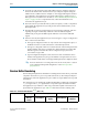
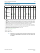


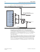
Table Of Contents
- Cyclone V Hard IP for PCI Express User Guide
- Contents
- 1. Datasheet
- 2. Getting Started with the Cyclone V Hard IP for PCI Express
- 3. Getting Started with the Avalon-MM Cyclone Hard IP for PCI Express
- Running Qsys
- Customizing the Cyclone VHard IP for PCI Express IP Core
- Adding the Remaining Components to the Qsys System
- Completing the Connections in Qsys
- Specifying Clocks and Interrupts
- Specifying Exported Interfaces
- Specifying Address Assignments
- Simulating the Example Design
- Simulating the Single DWord Design
- Understanding Channel Placement Guidelines
- Adding Synopsis Design Constraints
- Creating a Quartus II Project
- Compiling the Design
- Programming a Device
- 4. Parameter Settings for the Cyclone V Hard IP for PCI Express
- 5. Parameter Settings for the Avalon-MM Cyclone V Hard IP for PCI Express
- 6. IP Core Architecture
- Key Interfaces
- Protocol Layers
- Multi-Function Support
- PCI Express Avalon-MM Bridge
- Avalon-MM Bridge TLPs
- Avalon-MM-to-PCI Express Write Requests
- Avalon-MM-to-PCI Express Upstream Read Requests
- PCI Express-to-Avalon-MM Read Completions
- PCI Express-to-Avalon-MM Downstream Write Requests
- PCI Express-to-Avalon-MM Downstream Read Requests
- Avalon-MM-to-PCI Express Read Completions
- PCI Express-to-Avalon-MM Address Translation for Endpoints
- Minimizing BAR Sizes and the PCIe Address Space
- Avalon-MM-to-PCI Express Address Translation Algorithm
- Single DWord Completer Endpoint
- 7. IP Core Interfaces
- Cyclone V Hard IP for PCI Express
- Avalon-MM Hard IP for PCI Express
- Physical Layer Interface Signals
- Test Signals
- 8. Register Descriptions
- Configuration Space Register Content
- Altera-Defined Vendor Specific Extended Capability (VSEC)
- PCI Express Avalon-MM Bridge Control Register Access Content
- Avalon-MM to PCI Express Interrupt Registers
- PCI Express Mailbox Registers
- Avalon-MM-to-PCI Express Address Translation Table
- Root Port TLP Data Registers
- Programming Model for Avalon-MM Root Port
- PCI Express to Avalon-MM Interrupt Status and Enable Registers for Root Ports
- PCI Express to Avalon-MM Interrupt Status and Enable Registers for Endpoints
- Avalon-MM Mailbox Registers
- Correspondence between Configuration Space Registers and the PCIe Spec 2.1
- 9. Reset and Clocks
- 10. Transaction Layer Protocol (TLP) Details
- 11. Interrupts
- Interrupts for Endpoints Using the Avalon-ST Application Interface
- Interrupts for Root Ports Using the Avalon-ST Interface to the Application Layer
- Interrupts for Endpoints Using the Avalon-MM Interface to the Application Layer
- Interrupts for End Points Using the Avalon-MM Interface with Multiple MSI/MSI-X Support
- 12. Optional Features
- 13. Flow Control
- 14. Error Handling
- 15. Transceiver PHY IP Reconfiguration
- 16. SDC Timing Constraints
- 17. Testbench and Design Example
- Endpoint Testbench
- Root Port Testbench
- Chaining DMA Design Examples
- Test Driver Module
- Root Port Design Example
- Root Port BFM
- BFM Procedures and Functions
- 18. Debugging
- A. Transaction Layer Packet (TLP) Header Formats
- Additional Information

Chapter 10: Transaction Layer Protocol (TLP) Details 10–3
Transaction Layer Routing Rules
December 2013 Altera Corporation Cyclone V Hard IP for PCI Express
User Guide
Transaction Layer Routing Rules
Transactions adhere to the following routing rules:
■ In the receive direction (from the PCI Express link), memory and I/O requests that
match the defined base address register (BAR) contents and vendor-defined
messages with or without data route to the receive interface. The Application
Layer logic processes the requests and generates the read completions, if needed.
■ In Endpoint mode, received Type 0 Configuration requests from the PCI Express
upstream port route to the internal Configuration Space and the Cyclone V Hard
IP for PCI Express generates and transmits the completion.
■ The Hard IP handles supported received message transactions (Power
Management and Slot Power Limit) internally. The Endpoint also supports the
Unlock and Type 1 Messages. The Root Port supports Interrupt, Type 1 and error
Messages.
■ Vendor-defined Type 0 Message TLPs are passed to the Application Layer.
■ The Transaction Layer treats all other received transactions (including memory or
I/O requests that do not match a defined BAR) as Unsupported Requests. The
Transaction Layer sets the appropriate error bits and transmits a completion, if
needed. These Unsupported Requests are not made visible to the Application
Layer; the header and data is dropped.
Hot Plug Messages
Attention_indicator On Transmit Receive No Yes No
As per the recommendations in the
PCI
Express Base Specification Revision 2.1
,
these messages are not transmitted to the
Application Layer.
Attention_Indicator
Blink
Transmit Receive No Yes No
Attention_indicator_
Off
Transmit Receive No Yes No
Power_Indicator On Transmit Receive No Yes No
Power_Indicator Blink Transmit Receive No Yes No
Power_Indicator Off Transmit Receive No Yes No
Attention
Button_Pressed
(1)
Receive Transmit No No Yes
Notes to Table 10–1:
(1) In Endpoint mode.
(2) In the PCI Express Base Specification Revision 2.1, this message is no longer mandatory after link training.
Table 10–1. Supported Message Types
(2)
(Part 3 of 3)
Message
Root
Port
Endpoint
Generated by
Comments
App
Layer
Core
Core (with
App Layer
input)