
User guide
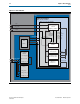


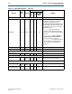
Table Of Contents
- Cyclone V Hard IP for PCI Express User Guide
- Contents
- 1. Datasheet
- 2. Getting Started with the Cyclone V Hard IP for PCI Express
- 3. Getting Started with the Avalon-MM Cyclone Hard IP for PCI Express
- Running Qsys
- Customizing the Cyclone VHard IP for PCI Express IP Core
- Adding the Remaining Components to the Qsys System
- Completing the Connections in Qsys
- Specifying Clocks and Interrupts
- Specifying Exported Interfaces
- Specifying Address Assignments
- Simulating the Example Design
- Simulating the Single DWord Design
- Understanding Channel Placement Guidelines
- Adding Synopsis Design Constraints
- Creating a Quartus II Project
- Compiling the Design
- Programming a Device
- 4. Parameter Settings for the Cyclone V Hard IP for PCI Express
- 5. Parameter Settings for the Avalon-MM Cyclone V Hard IP for PCI Express
- 6. IP Core Architecture
- Key Interfaces
- Protocol Layers
- Multi-Function Support
- PCI Express Avalon-MM Bridge
- Avalon-MM Bridge TLPs
- Avalon-MM-to-PCI Express Write Requests
- Avalon-MM-to-PCI Express Upstream Read Requests
- PCI Express-to-Avalon-MM Read Completions
- PCI Express-to-Avalon-MM Downstream Write Requests
- PCI Express-to-Avalon-MM Downstream Read Requests
- Avalon-MM-to-PCI Express Read Completions
- PCI Express-to-Avalon-MM Address Translation for Endpoints
- Minimizing BAR Sizes and the PCIe Address Space
- Avalon-MM-to-PCI Express Address Translation Algorithm
- Single DWord Completer Endpoint
- 7. IP Core Interfaces
- Cyclone V Hard IP for PCI Express
- Avalon-MM Hard IP for PCI Express
- Physical Layer Interface Signals
- Test Signals
- 8. Register Descriptions
- Configuration Space Register Content
- Altera-Defined Vendor Specific Extended Capability (VSEC)
- PCI Express Avalon-MM Bridge Control Register Access Content
- Avalon-MM to PCI Express Interrupt Registers
- PCI Express Mailbox Registers
- Avalon-MM-to-PCI Express Address Translation Table
- Root Port TLP Data Registers
- Programming Model for Avalon-MM Root Port
- PCI Express to Avalon-MM Interrupt Status and Enable Registers for Root Ports
- PCI Express to Avalon-MM Interrupt Status and Enable Registers for Endpoints
- Avalon-MM Mailbox Registers
- Correspondence between Configuration Space Registers and the PCIe Spec 2.1
- 9. Reset and Clocks
- 10. Transaction Layer Protocol (TLP) Details
- 11. Interrupts
- Interrupts for Endpoints Using the Avalon-ST Application Interface
- Interrupts for Root Ports Using the Avalon-ST Interface to the Application Layer
- Interrupts for Endpoints Using the Avalon-MM Interface to the Application Layer
- Interrupts for End Points Using the Avalon-MM Interface with Multiple MSI/MSI-X Support
- 12. Optional Features
- 13. Flow Control
- 14. Error Handling
- 15. Transceiver PHY IP Reconfiguration
- 16. SDC Timing Constraints
- 17. Testbench and Design Example
- Endpoint Testbench
- Root Port Testbench
- Chaining DMA Design Examples
- Test Driver Module
- Root Port Design Example
- Root Port BFM
- BFM Procedures and Functions
- 18. Debugging
- A. Transaction Layer Packet (TLP) Header Formats
- Additional Information
9–4 Chapter 9: Reset and Clocks
Clocks
Cyclone V Hard IP for PCI Express December 2013 Altera Corporation
User Guide
As Figure 9–3 illustrates, the RX transceiver reset includes the following steps:
1. After
rx_pll_locked
is asserted, the LTSSM state machine transitions from the
Detect.Quiet to the Detect.Active state.
2. When the
pipe_phystatus
pulse is asserted and
pipe_rxstatus[2:0]
= 3, the
receiver detect operation has completed.
3. The LTSSM state machine transitions from the Detect.Active state to the
Polling.Active state.
4. The Hard IP for PCI Express asserts
rx_digitalreset
. The
rx_digitalreset
signal
is deasserted after
rx_signaldetect
is stable for a minimum of 3 ms.
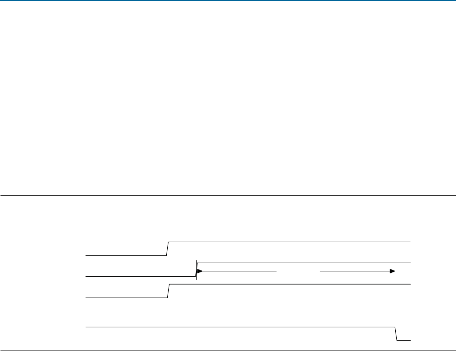
Figure 9–4 illustrates the TX transceiver reset sequence.
As Figure 9–4 illustrates, the RX transceiver reset includes the following steps:
1. After
npor
is deasserted, the core deasserts the
npor_serdes
input to the TX
transceiver.
2. The SERDES reset controller waits for
pll_locked
to be stable for a minimum of
127 cycles before deasserting
tx_digitalreset.
1 The Cyclone V embedded reset sequence meets the 100 ms configuration time
specified in the PCI Express Base Specification 2.1.
Clocks
In accordance with the PCI Express Base Specification 2.1, you must provide a 100 MHz
reference clock that is connected directly to the transceiver. As a convenience, you
may also use a 125 MHz input reference clock as input to the TX PLL. The output of
the transceiver drives
coreclkout_hip
.
coreclkout_hip
must be connected back to
the
pld_clk
input clock, possibly through a clock distribution circuit required by the
specific application.
Figure 9–4. TX Transceiver Reset Sequence
npor
pll_locked
npor_serdes
127 cycles
tx_digitalreset