
User guide
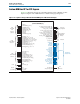
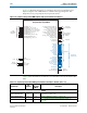
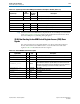
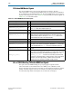
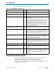
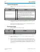
Table Of Contents
- Cyclone V Hard IP for PCI Express User Guide
- Contents
- 1. Datasheet
- 2. Getting Started with the Cyclone V Hard IP for PCI Express
- 3. Getting Started with the Avalon-MM Cyclone Hard IP for PCI Express
- Running Qsys
- Customizing the Cyclone VHard IP for PCI Express IP Core
- Adding the Remaining Components to the Qsys System
- Completing the Connections in Qsys
- Specifying Clocks and Interrupts
- Specifying Exported Interfaces
- Specifying Address Assignments
- Simulating the Example Design
- Simulating the Single DWord Design
- Understanding Channel Placement Guidelines
- Adding Synopsis Design Constraints
- Creating a Quartus II Project
- Compiling the Design
- Programming a Device
- 4. Parameter Settings for the Cyclone V Hard IP for PCI Express
- 5. Parameter Settings for the Avalon-MM Cyclone V Hard IP for PCI Express
- 6. IP Core Architecture
- Key Interfaces
- Protocol Layers
- Multi-Function Support
- PCI Express Avalon-MM Bridge
- Avalon-MM Bridge TLPs
- Avalon-MM-to-PCI Express Write Requests
- Avalon-MM-to-PCI Express Upstream Read Requests
- PCI Express-to-Avalon-MM Read Completions
- PCI Express-to-Avalon-MM Downstream Write Requests
- PCI Express-to-Avalon-MM Downstream Read Requests
- Avalon-MM-to-PCI Express Read Completions
- PCI Express-to-Avalon-MM Address Translation for Endpoints
- Minimizing BAR Sizes and the PCIe Address Space
- Avalon-MM-to-PCI Express Address Translation Algorithm
- Single DWord Completer Endpoint
- 7. IP Core Interfaces
- Cyclone V Hard IP for PCI Express
- Avalon-MM Hard IP for PCI Express
- Physical Layer Interface Signals
- Test Signals
- 8. Register Descriptions
- Configuration Space Register Content
- Altera-Defined Vendor Specific Extended Capability (VSEC)
- PCI Express Avalon-MM Bridge Control Register Access Content
- Avalon-MM to PCI Express Interrupt Registers
- PCI Express Mailbox Registers
- Avalon-MM-to-PCI Express Address Translation Table
- Root Port TLP Data Registers
- Programming Model for Avalon-MM Root Port
- PCI Express to Avalon-MM Interrupt Status and Enable Registers for Root Ports
- PCI Express to Avalon-MM Interrupt Status and Enable Registers for Endpoints
- Avalon-MM Mailbox Registers
- Correspondence between Configuration Space Registers and the PCIe Spec 2.1
- 9. Reset and Clocks
- 10. Transaction Layer Protocol (TLP) Details
- 11. Interrupts
- Interrupts for Endpoints Using the Avalon-ST Application Interface
- Interrupts for Root Ports Using the Avalon-ST Interface to the Application Layer
- Interrupts for Endpoints Using the Avalon-MM Interface to the Application Layer
- Interrupts for End Points Using the Avalon-MM Interface with Multiple MSI/MSI-X Support
- 12. Optional Features
- 13. Flow Control
- 14. Error Handling
- 15. Transceiver PHY IP Reconfiguration
- 16. SDC Timing Constraints
- 17. Testbench and Design Example
- Endpoint Testbench
- Root Port Testbench
- Chaining DMA Design Examples
- Test Driver Module
- Root Port Design Example
- Root Port BFM
- BFM Procedures and Functions
- 18. Debugging
- A. Transaction Layer Packet (TLP) Header Formats
- Additional Information

Chapter 7: IP Core Interfaces 7–47
Physical Layer Interface Signals
December 2013 Altera Corporation Cyclone V Hard IP for PCI Express
User Guide
Table 7–22 lists the TX slave interface signals.
Physical Layer Interface Signals
This section describes the global PHY support signals for the internal PHY. The
MegaWizard Plug-In Manager generates a SERDES variation file,
<variation>_serdes.<v or vhd >, in addition of the Hard IP variation file,
<variation>.<v or vhd>. For Cyclone V GX devices the SERDES entity is included in
the library files for PCI Express.
Table 7–22. Avalon-MM TX Slave Interface Signals
Signal Name I/O Description
TxsChipSelect_i
I
The system interconnect fabric asserts this signal to select the TX
slave port.
TxsRead_i
I
Read request asserted by the system interconnect fabric to
request a read.
TxsWrite_i
I
Write request asserted by the system interconnect fabric to
request a write.
The Avalon-MM Cyclone V Hard IP for PCI Express requires that
the Avalon-MM master assert this signal continuously from the
first data phase through the final data phase of the burst. The
Avalon-MM master Application Layer must guarantee the data
can be passed to the interconnect fabric with no pauses. This
behavior is most easily implemented with a store and forward
buffer in the Avalon-MM master.
TxsWritedata_i[63:0 or 127:0]
I
Write data sent by the external Avalon-MM master to the TX slave
port.
TxsBurstCount_i[6:0 or 5:0]
I
Asserted by the system interconnect fabric indicating the amount
of data requested. The count unit is the amount of data that is
transferred in a single cycle, that is, the width of the bus. Because
the maximum data per burst is 512 bytes,
TxmBurstCount
is 6
bits for the 64-bit interface and 5 bits for the 128-bit interface.
TxsAddress_i[<w>-1:0]
I
Address of the read or write request from the external Avalon-MM
master. This address translates to 64-bit or 32-bit PCI Express
addresses based on the translation table. The
<w>
value is
determined when the system is created.
TxsBytEnable_i[7:0 or 15:0]
I
Write byte enable for data. A burst must be continuous. Therefore
all intermediate data phases of a burst must have a byte enable
value of 0xFF. The first and final data phases of a burst can have
other valid values.
TxsReadDataValid_o
O Asserted by the bridge to indicate that read data is valid.
TxsReadData_o[63:0 or 128:0]
O
The bridge returns the read data on this bus when the RX read
completions for the read have been received and stored in the
internal buffer.
TxsWaitrequest_o
O
Asserted by the bridge to hold off write data when running out of
buffer space. If this signal is asserted during an operation, the
master should maintain the
txs_Read
signal (or
txs_Write
signal and
txs_WriteData
) stable until after
txs_WaitRequest
is deasserted.