
User guide
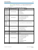
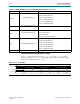
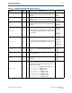
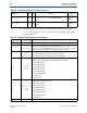
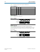
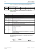
Table Of Contents
- Cyclone V Hard IP for PCI Express User Guide
- Contents
- 1. Datasheet
- 2. Getting Started with the Cyclone V Hard IP for PCI Express
- 3. Getting Started with the Avalon-MM Cyclone Hard IP for PCI Express
- Running Qsys
- Customizing the Cyclone VHard IP for PCI Express IP Core
- Adding the Remaining Components to the Qsys System
- Completing the Connections in Qsys
- Specifying Clocks and Interrupts
- Specifying Exported Interfaces
- Specifying Address Assignments
- Simulating the Example Design
- Simulating the Single DWord Design
- Understanding Channel Placement Guidelines
- Adding Synopsis Design Constraints
- Creating a Quartus II Project
- Compiling the Design
- Programming a Device
- 4. Parameter Settings for the Cyclone V Hard IP for PCI Express
- 5. Parameter Settings for the Avalon-MM Cyclone V Hard IP for PCI Express
- 6. IP Core Architecture
- Key Interfaces
- Protocol Layers
- Multi-Function Support
- PCI Express Avalon-MM Bridge
- Avalon-MM Bridge TLPs
- Avalon-MM-to-PCI Express Write Requests
- Avalon-MM-to-PCI Express Upstream Read Requests
- PCI Express-to-Avalon-MM Read Completions
- PCI Express-to-Avalon-MM Downstream Write Requests
- PCI Express-to-Avalon-MM Downstream Read Requests
- Avalon-MM-to-PCI Express Read Completions
- PCI Express-to-Avalon-MM Address Translation for Endpoints
- Minimizing BAR Sizes and the PCIe Address Space
- Avalon-MM-to-PCI Express Address Translation Algorithm
- Single DWord Completer Endpoint
- 7. IP Core Interfaces
- Cyclone V Hard IP for PCI Express
- Avalon-MM Hard IP for PCI Express
- Physical Layer Interface Signals
- Test Signals
- 8. Register Descriptions
- Configuration Space Register Content
- Altera-Defined Vendor Specific Extended Capability (VSEC)
- PCI Express Avalon-MM Bridge Control Register Access Content
- Avalon-MM to PCI Express Interrupt Registers
- PCI Express Mailbox Registers
- Avalon-MM-to-PCI Express Address Translation Table
- Root Port TLP Data Registers
- Programming Model for Avalon-MM Root Port
- PCI Express to Avalon-MM Interrupt Status and Enable Registers for Root Ports
- PCI Express to Avalon-MM Interrupt Status and Enable Registers for Endpoints
- Avalon-MM Mailbox Registers
- Correspondence between Configuration Space Registers and the PCIe Spec 2.1
- 9. Reset and Clocks
- 10. Transaction Layer Protocol (TLP) Details
- 11. Interrupts
- Interrupts for Endpoints Using the Avalon-ST Application Interface
- Interrupts for Root Ports Using the Avalon-ST Interface to the Application Layer
- Interrupts for Endpoints Using the Avalon-MM Interface to the Application Layer
- Interrupts for End Points Using the Avalon-MM Interface with Multiple MSI/MSI-X Support
- 12. Optional Features
- 13. Flow Control
- 14. Error Handling
- 15. Transceiver PHY IP Reconfiguration
- 16. SDC Timing Constraints
- 17. Testbench and Design Example
- Endpoint Testbench
- Root Port Testbench
- Chaining DMA Design Examples
- Test Driver Module
- Root Port Design Example
- Root Port BFM
- BFM Procedures and Functions
- 18. Debugging
- A. Transaction Layer Packet (TLP) Header Formats
- Additional Information

Chapter 7: IP Core Interfaces 7–41
Cyclone V Hard IP for PCI Express
December 2013 Altera Corporation Cyclone V Hard IP for PCI Express
User Guide
Power Management Signals
Table 7–16 describes the power management signals.
Table 7–16. Power Management Signals
Signal I/O Description
pme_to_cr
I
Power management turn off control register.
Root Port—When this signal is asserted, the Root Port sends the
PME_turn_off
message.
Endpoint—This signal is asserted to acknowledge the
PME_turn_off
message by sending
pme_to_ack
to the Root Port.
pme_to_sr
O
Power management turn off status register.
Root Port—This signal is asserted for 1 clock cycle when the Root Port receives the
pme_turn_off
acknowledge message.
Endpoint—This signal is asserted for 1 cycle when the Endpoint receives the
PME_turn_off
message from the Root Port.
pm_event
I
Power Management Event. This signal is only available for Endpoints.
The Endpoint initiates a a
power_management_event
message (PM_PME) that is sent to
the Root Port. If the Hard IP is in a low power state, the link exists from the low-power state
to send the message. This signal is positive edge-sensitive.
pm_event_func[2:0]
I Specifies the function associated with a Power Management Event.
pm_data[9:0]
I
Power Management Data.
This bus indicates power consumption of the component. This bus can only be
implemented if all three bits of
AUX_power
(part of the Power Management Capabilities
structure) are set to 0. This bus includes the following bits:
■
pm_data[9:2]
: Data Register: This register maintains a value associated with the power
consumed by the component. (Refer to the example below)
■
pm_data[1:0]
: Data Scale: This register maintains the scale used to find the power
consumed by a particular component and can include the following values:
b’00: unknown
b’01: 0.1 ×
b’10: 0.01 ×
b’11: 0.001 ×
For example, the two registers might have the following values:
■
pm_data[9:2]
: b’1110010 = 114
■
pm_data[1:0]
: b’10, which encodes a factor of 0.01
To find the maximum power consumed by this component, multiply the data value by the
data Scale (114 × .01 = 1.14). 1.14 watts is the maximum power allocated to this
component in the power state selected by the
data_select
field.
pm_auxpwr
I
Power Management Auxiliary Power: This signal can be tied to 0 because the L2 power
state is not supported.