
User guide


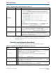

Table Of Contents
- Cyclone V Hard IP for PCI Express User Guide
- Contents
- 1. Datasheet
- 2. Getting Started with the Cyclone V Hard IP for PCI Express
- 3. Getting Started with the Avalon-MM Cyclone Hard IP for PCI Express
- Running Qsys
- Customizing the Cyclone VHard IP for PCI Express IP Core
- Adding the Remaining Components to the Qsys System
- Completing the Connections in Qsys
- Specifying Clocks and Interrupts
- Specifying Exported Interfaces
- Specifying Address Assignments
- Simulating the Example Design
- Simulating the Single DWord Design
- Understanding Channel Placement Guidelines
- Adding Synopsis Design Constraints
- Creating a Quartus II Project
- Compiling the Design
- Programming a Device
- 4. Parameter Settings for the Cyclone V Hard IP for PCI Express
- 5. Parameter Settings for the Avalon-MM Cyclone V Hard IP for PCI Express
- 6. IP Core Architecture
- Key Interfaces
- Protocol Layers
- Multi-Function Support
- PCI Express Avalon-MM Bridge
- Avalon-MM Bridge TLPs
- Avalon-MM-to-PCI Express Write Requests
- Avalon-MM-to-PCI Express Upstream Read Requests
- PCI Express-to-Avalon-MM Read Completions
- PCI Express-to-Avalon-MM Downstream Write Requests
- PCI Express-to-Avalon-MM Downstream Read Requests
- Avalon-MM-to-PCI Express Read Completions
- PCI Express-to-Avalon-MM Address Translation for Endpoints
- Minimizing BAR Sizes and the PCIe Address Space
- Avalon-MM-to-PCI Express Address Translation Algorithm
- Single DWord Completer Endpoint
- 7. IP Core Interfaces
- Cyclone V Hard IP for PCI Express
- Avalon-MM Hard IP for PCI Express
- Physical Layer Interface Signals
- Test Signals
- 8. Register Descriptions
- Configuration Space Register Content
- Altera-Defined Vendor Specific Extended Capability (VSEC)
- PCI Express Avalon-MM Bridge Control Register Access Content
- Avalon-MM to PCI Express Interrupt Registers
- PCI Express Mailbox Registers
- Avalon-MM-to-PCI Express Address Translation Table
- Root Port TLP Data Registers
- Programming Model for Avalon-MM Root Port
- PCI Express to Avalon-MM Interrupt Status and Enable Registers for Root Ports
- PCI Express to Avalon-MM Interrupt Status and Enable Registers for Endpoints
- Avalon-MM Mailbox Registers
- Correspondence between Configuration Space Registers and the PCIe Spec 2.1
- 9. Reset and Clocks
- 10. Transaction Layer Protocol (TLP) Details
- 11. Interrupts
- Interrupts for Endpoints Using the Avalon-ST Application Interface
- Interrupts for Root Ports Using the Avalon-ST Interface to the Application Layer
- Interrupts for Endpoints Using the Avalon-MM Interface to the Application Layer
- Interrupts for End Points Using the Avalon-MM Interface with Multiple MSI/MSI-X Support
- 12. Optional Features
- 13. Flow Control
- 14. Error Handling
- 15. Transceiver PHY IP Reconfiguration
- 16. SDC Timing Constraints
- 17. Testbench and Design Example
- Endpoint Testbench
- Root Port Testbench
- Chaining DMA Design Examples
- Test Driver Module
- Root Port Design Example
- Root Port BFM
- BFM Procedures and Functions
- 18. Debugging
- A. Transaction Layer Packet (TLP) Header Formats
- Additional Information

Chapter 7: IP Core Interfaces 7–25
Cyclone V Hard IP for PCI Express
December 2013 Altera Corporation Cyclone V Hard IP for PCI Express
User Guide
Reset Signals
Table 7–6 describes the reset signals.
Table 7–6. Reset and Link Training Signals (Part 1 of 3)
Signal I/O Description
npor
I
Active low reset signal. It is the
OR
of
pin_perstn
and the
local_rstn
signal coming from
software Application Layer. If you do not drive a soft reset signal from the Application Layer,
this signal must be derived from
pin_perstn.
You cannot disable this signal.
reset_status
O
Active high reset status signal. When asserted, this signal indicates that the Hard IP clock is
in reset. The
reset_status
signal is synchronous to the
pld_clk
clock and is deasserted
only when the
npor
is deasserted and the Hard IP for PCI Express is not in reset
(
reset_status_hip
= 0). You should use
reset_status
to drive the reset of your
application.
nreset_status
O
For the Hard IP for PCI Express IP Core using the Avalon-MM interface,
nreset_status
is
an active low reset signal.
apps_rstn
, which is derived from
npor
or
pin_perstn
drives
nreset_status.
pin_perstn
I
Active low reset from the PCIe reset pin of the device. This reset signal is an input to the
embedded reset controller for PCI Express in Cyclone V devices. It resets the datapath and
control registers. This signal is required for CvP.
Although CvP is not supported in the current release, Altera is providing the following
information about the placement of the
pin_perstn
pins to facilitate advanced layout of
PCBs. Cyclone V devices have 1 or 2 instances of the Hard IP for PCI Express. Each instance
has its own
pin_perstn
signal.
Cyclone V devices have a
nPERST
pin for each available instance of the Hard IP for PCI
Express. These pins have the following locations:
■
nPERSTL0
: Top left Hard IP
■
nPERSTL1
: Bottom left Hard IP and CvP blocks
For maximum use of the Cyclone V device, Altera recommends that you use the bottom left
Hard IP first. This is the only location that supports CvP over a PCIe link.
Refer to the appropriate Cyclone V device pinout for correct pin assignment for more
detailed information about these pins. The PCI Express Card Electromechanical Specification
2.0 specifies this pin to require 3.3 V. You can drive this 3.3V signal to the
pin_perst
pin
even if the V
CCIO
of the bank is not 3.3V if the following 2 conditions are met:
■ The input signal meets the V
IH
and V
IL
specification for LVTTL.
■
■
The input signal meets the overshoot specification for 100C operation as specified by the
“Maximum Allowed Overshoot and Undershoot Voltage” section in the Device Datasheet
for Cyclone V Devices in volume 1 of the Cyclone Device Handbook.
Refer to Figure 7–29 on page 7–27 for a timing diagram illustrating the use of this signal.
serdes_pll_locked
O
When asserted, indicates that the PLL that generates the
coreclkout_hip
clock signal is
locked. In pipe simulation mode this signal is always asserted.
pld_core_ready
I
When asserted, indicates that the Application Layer is ready for operation and is providing a
stable clock to the
pld_clk
input. If the
coreclkout_hip
Hard IP output clock is sourcing
the
pld_clk
Hard IP input, this input can be connected to the
serdes_pll_locked
output.