
User guide

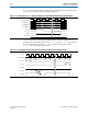
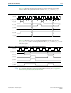


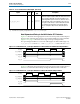
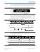
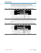

Table Of Contents
- Cyclone V Hard IP for PCI Express User Guide
- Contents
- 1. Datasheet
- 2. Getting Started with the Cyclone V Hard IP for PCI Express
- 3. Getting Started with the Avalon-MM Cyclone Hard IP for PCI Express
- Running Qsys
- Customizing the Cyclone VHard IP for PCI Express IP Core
- Adding the Remaining Components to the Qsys System
- Completing the Connections in Qsys
- Specifying Clocks and Interrupts
- Specifying Exported Interfaces
- Specifying Address Assignments
- Simulating the Example Design
- Simulating the Single DWord Design
- Understanding Channel Placement Guidelines
- Adding Synopsis Design Constraints
- Creating a Quartus II Project
- Compiling the Design
- Programming a Device
- 4. Parameter Settings for the Cyclone V Hard IP for PCI Express
- 5. Parameter Settings for the Avalon-MM Cyclone V Hard IP for PCI Express
- 6. IP Core Architecture
- Key Interfaces
- Protocol Layers
- Multi-Function Support
- PCI Express Avalon-MM Bridge
- Avalon-MM Bridge TLPs
- Avalon-MM-to-PCI Express Write Requests
- Avalon-MM-to-PCI Express Upstream Read Requests
- PCI Express-to-Avalon-MM Read Completions
- PCI Express-to-Avalon-MM Downstream Write Requests
- PCI Express-to-Avalon-MM Downstream Read Requests
- Avalon-MM-to-PCI Express Read Completions
- PCI Express-to-Avalon-MM Address Translation for Endpoints
- Minimizing BAR Sizes and the PCIe Address Space
- Avalon-MM-to-PCI Express Address Translation Algorithm
- Single DWord Completer Endpoint
- 7. IP Core Interfaces
- Cyclone V Hard IP for PCI Express
- Avalon-MM Hard IP for PCI Express
- Physical Layer Interface Signals
- Test Signals
- 8. Register Descriptions
- Configuration Space Register Content
- Altera-Defined Vendor Specific Extended Capability (VSEC)
- PCI Express Avalon-MM Bridge Control Register Access Content
- Avalon-MM to PCI Express Interrupt Registers
- PCI Express Mailbox Registers
- Avalon-MM-to-PCI Express Address Translation Table
- Root Port TLP Data Registers
- Programming Model for Avalon-MM Root Port
- PCI Express to Avalon-MM Interrupt Status and Enable Registers for Root Ports
- PCI Express to Avalon-MM Interrupt Status and Enable Registers for Endpoints
- Avalon-MM Mailbox Registers
- Correspondence between Configuration Space Registers and the PCIe Spec 2.1
- 9. Reset and Clocks
- 10. Transaction Layer Protocol (TLP) Details
- 11. Interrupts
- Interrupts for Endpoints Using the Avalon-ST Application Interface
- Interrupts for Root Ports Using the Avalon-ST Interface to the Application Layer
- Interrupts for Endpoints Using the Avalon-MM Interface to the Application Layer
- Interrupts for End Points Using the Avalon-MM Interface with Multiple MSI/MSI-X Support
- 12. Optional Features
- 13. Flow Control
- 14. Error Handling
- 15. Transceiver PHY IP Reconfiguration
- 16. SDC Timing Constraints
- 17. Testbench and Design Example
- Endpoint Testbench
- Root Port Testbench
- Chaining DMA Design Examples
- Test Driver Module
- Root Port Design Example
- Root Port BFM
- BFM Procedures and Functions
- 18. Debugging
- A. Transaction Layer Packet (TLP) Header Formats
- Additional Information

7–16 Chapter 7: IP Core Interfaces
Cyclone V Hard IP for PCI Express
Cyclone V Hard IP for PCI Express December 2013 Altera Corporation
User Guide
Avalon-ST TX Interface
Table 7–4 describes the signals that comprise the Avalon-ST TX Datapath. The TX data
signal can be 64 or 128 bits.
Table 7–4. 64- or 128-Bit Avalon-ST TX Datapath (Part 1 of 4)
Signal Width Dir
Avalon-ST
Type
Description
tx_st_data
6412
8
I
data
Data for transmission. Transmit data bus. Refer to
Figure 7–18 through Figure 7–22 for the mapping of TLP
packets to
tx_st_data
and examples of the timing of the
64-bit interface. Refer to Figure 7–23 through Figure 7–28
for the mapping of TLP packets to
tx_st_data
and
examples of the timing of the 128-bit interface.
The Application Layer must provide a properly formatted
TLP on the TX interface. The mapping of message TLPs is
the same as the mapping of Transaction Layer TLPs with 4
dword headers. The number of data cycles must be correct
for the length and address fields in the header. Issuing a
packet with an incorrect number of data cycles results in
the TX interface hanging and unable to accept further
requests.
tx_st_sop
1I
start of
packet
Indicates first cycle of a TLP when asserted in the same
cycle with
tx_st_valid
.
tx_st_eop
1I
end of
packet
Indicates last cycle of a TLP when asserted in the same
cycle with
tx_st_valid
.
tx_st_ready
(1)
1O
ready
Indicates that the Transaction Layer is ready to accept data
for transmission. The core deasserts this signal to throttle
the data stream.
tx_st_ready
may be asserted during
reset. The Application Layer should wait at least 2 clock
cycles after the reset is released before issuing packets on
the Avalon-ST TX interface. The
reset_status
signal can
also be used to monitor when the Hard IP has come out of
reset.
If
tx_st_ready
is asserted by the Transaction Layer on
cycle <n>, then <n +
readyLatency
> is a ready cycle,
during which the Application Layer may assert
valid
and
transfer data.
When
tx_st_ready
,
tx_st_valid
and
tx_st_data
are
registered (the typical case), Altera recommends a
readyLatency
of 2 cycles to facilitate timing closure;
however, a
readyLatency
of 1 cycle is possible.