
Specifications

Design Guidelines & Procedures Version 18 ©
Electrical Services Section 20.00 / Page 23
20.18 Electrical Design Requirements
The electrical design submitted for review by the CLF Electrical Engineer shall, as a minimum
requirement, include the following;
Maximum demand calculations for each switchboard, net and with spare capacity;
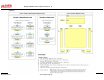
Voltage drop schematic, eg from substation to MSB to DB to load centre (where
applicable) to socket outlet or permanent connection.
Line diagram schematic of the main switchboard with fault current withstand rating, size
and ratings of switchgear and cables entering or leaving the board.
Details of distribution boards including number of poles, rating of busbar and mainswitch
and number of spare poles.
Details of lightning protection, earthing schematic and fault loop impedances for non
RCD circuits.
Layout of cable tray/ladder routes
Layouts of underground services
Schedule of luminaire types and outlets
Luminaire layouts and switching/control schematics
Locations, types and classifications of emergency lighting.
All lighting and power drawings are to show the Circuit Breaker No. and distribution board
feeding the circuit. The use of ‘L’ and ‘P’ on the design, tender or ‘As Constructed’ drawings, will
not be accepted by CLF.
The written approval of the CLF Electrical Engineer must be obtained before issuing any
drawings for tender or construction.