
User guide


Virtex-5 FPGA Integrated Endpoint Block www.xilinx.com 91
UG197 (v1.5) July 22, 2009
R
Appendix A
Integrated Endpoint Block Attributes
Summary
This appendix lists the attributes that must be set for the Virtex-5 FPGA Integrated
Endpoint block. All attributes are set in the Endpoint Block Plus wrapper, based on choices
made in the CORE Generator GUI, and are documented here for reference.
• “TX and RX Buffer Layout”
• “Buffer Latency”
• “Initial Flow Control Credits”
• “Extended Capabilities”
• “Integrated Endpoint Block Attributes”
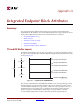
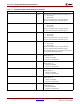
TX and RX Buffer Layout
Each buffer is divided into separate areas for posted, non-posted, and completion packets.
No gaps can be in the FIFO base and limit attribute settings, and they must be in the order
shown in Figure A-1.
The selection of the FIFO base and FIFO limit attribute values for any packet type can be
determined by the amount of RAM available to allocate, the number of packets to be to
accommodated in the FIFO at any given time, and the size of those packets. One way of
determining the necessary FIFO size is to multiply the maximum packet size by the
number of packets. A smaller FIFO could be used, or a larger number of packets
accommodated, if the pattern of traffic is such that maximum-sized packets are
Figure A-1: Layout for TX and RX Buffers
VC0{RX/TX}FIFOBASEP
VC0{RX/TX}FIFOBASENP
VC0{RX/TX}FIFOBASEC
VC0{RX/TX}FIFOLIMITNP
VC0{RX/TX}FIFOLIMITP
VC0{RX/TX}FIFOLIMITC
{}
VC0
Posted
Non-Posted
Completion
UG197_a_01_112106