
User guide

Virtex-5 FPGA Integrated Endpoint Block www.xilinx.com 77
UG197 (v1.5) July 22, 2009
Lane Width
R
Lane Width
The maximum number of lanes supported by a design using the integrated Endpoint block
can be specified through the
ACTIVELANESIN and LINKCAPABILITYMAXLINKWIDTH
attributes. These attributes should specify the same number of lanes, and a RocketIO
transceiver should be connected to the integrated Endpoint block through the Transceiver
interface for each lane specified. This is automatically configured and connected based on
choices made in the CORE Generator GUI of the Endpoint Block Plus Wrapper.
If a design using the integrated Endpoint block is plugged into a slot having fewer lanes
than the configuration of the integrated Endpoint block, or if lane(s) are broken, the
integrated Endpoint block auto-negotiates a smaller lane width with the link partner. The
following lane width auto-negotiations are supported:
• x8 to x4, x2 or x1
• x4 to x2 or x1
• x2 to x1
The negotiated lane width is indicated by the
L0MACNEGOTIATEDLINKWIDTH output once
the link has entered L0.
Once a link has been retrained to a lower than maximum supported link width, it is unable
to retrain back up to a higher link width through recovery. A complete receiver detect
sequence is required to configure the design to a higher link width. This can be done by
resetting the integrated Endpoint block.
Lane Reversal
The integrated Endpoint block supports limited lane reversal capabilities and therefore
provides flexibility in the design of the board for the link partner. The link partner can
choose to layout the board with reversed lane numbers and the integrated Endpoint block
will continue to link train successfully and operate normally. The configurations that have
lane reversal support are x8 and x4 (excluding downshift modes). Downshift refers to the
link width negotiation process that occurs when link partners have different lane width
capabilities advertised. As a result of lane width negotiation, the link partners negotiate
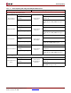
down to the smaller of the two advertised lane widths. Table 4-5 describes the several
possible combinations including downshift modes and availability of lane reversal
support.
Table 4-5: Lane Reversal Support
Endpoint Block
Advertised
Lane Width
Negotiated
Lane Width
Lane Number Mapping
(Endpoint → Link Partner)
Lane
Reversal
Supported
Endpoint Link Partner
x8 x8 Lane 0 … Lane 7 Lane 7 … Lane 0 Yes
x8 x4 Lane 0 … Lane 3 Lane 7 … Lane 4 No
(1)
x8 x2 Lane 0 … Lane 3 Lane 7… Lane 6 No
(1)
x4 x4 Lane 0 … Lane 3 Lane 3 … Lane 0 Yes
x4 x2 Lane 0 … Lane 1 Lane 3 … Lane 2 No
(1)
Notes:
1. When the lanes are reversed in the board layout and a downshift adapter card is inserted
between the Endpoint and link partner, Lane 0 of the link partner remains unconnected (as
shown by the lane mapping in Table 4-5) and therefore does not link train.