
User guide

54 www.xilinx.com Virtex-5 FPGA Integrated Endpoint Block
UG197 (v1.5) July 22, 2009
Chapter 2: Integrated Endpoint Block Functionality
R
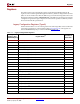
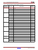
Power Management Capability Registers
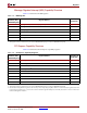
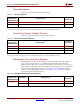
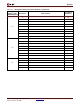
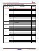
Table 2-18 summarizes the Power Management Capability Structure registers.
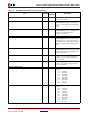
16 Reserved RO
17 Reserved RO
18 Reserved RO
19 Reserved RO
1A Reserved RO
1B Reserved RO
1C Reserved RO
Notes:
1. The register names are listed as they are read on MGMTRDATA[31:0] or written to MGMTWDATA[31:0].
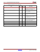
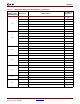
2. The number of Base Address registers implemented depends on the BARnEXIST attribute settings, while the width of the Address
range allocated by the host depends on the Base Address Register Mask, set from the BARnMASKWIDTH attributes.
Table 2-17: Legacy Configuration Registers (Continued)
Management
Address (Hex)
MGMTADDR[10:0]
Register Name
(1)
Read Only or
Read Write
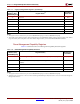
Table 2-18: Power Management Capability Structure
Management
Address (Hex)
MGMTADDR[10:0]
Register Name
(1)
Read Only or
Read Write
1D Power Management Capabilities (PMC)
(2)
; Next Capability Pointer; Capability
ID
RW; RW; RO
1E Reserved (8 bits); Reserved (8 bits); Power Management Control/Status
(PMCSR)
N/A; N/A; RO
1F Reserved N/A
20 Reserved N/A
21 Reserved N/A
Notes:
1. The register names are listed as they are read on MGMTRDATA[31:0] or written to MGMTWDATA[31:0].
2. The PM version correctly has a value of 3 when read through the PCI Express link, but returns a value of 2 when read through the
Management interface.