
User guide

Virtex-5 FPGA Integrated Endpoint Block www.xilinx.com 49
UG197 (v1.5) July 22, 2009
Virtex-5 FPGA Integrated Endpoint Block Interface Descriptions
R
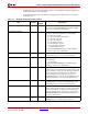
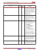
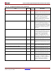
L0SETCOMPLETERABORTERROR
Input user_clk When asserted, causes the relevant
Completer Abort status bit(s) to be set
to 1.
L0SETDETECTEDCORRERROR
Input user_clk When asserted, causes the relevant
Correctable Error status bit(s) to be set
to 1. If bit 0 of the Device Control
Register is set (Correctable Error
Reporting Enable), then a Correctable
Error Message is also sent.
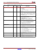
L0SETDETECTEDFATALERROR
Input user_clk When asserted, causes the relevant
Fatal Error status bit(s) to be set to 1. If
bit 2 of the Device Control Register is
set (Fatal Error Reporting Enable) or bit
8 of the Command Register is set (SERR
Enable), then a Fatal Error Message is
also sent.
L0SETDETECTEDNONFATALERROR
Input user_clk When asserted, causes the relevant
Nonfatal Error status bit(s) to be set to
1. If bit 1 of the Device Control Register
is set (Non-Fatal Error Reporting
Enable) or bit 8 of the Command
Register is set (SERR Enable), then a
Non-Fatal Error Message is also sent.
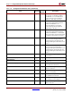
L0SETUSERDETECTEDPARITYERROR
Input user_clk When asserted, causes the relevant
Parity Error status bit(s) to be set to 1.
L0SETUSERMASTERDATAPARITY
Input user_clk When asserted, causes the relevant
Master Data Parity status bit(s) to be set
to 1.
L0SETUSERRECEIVEDMASTERABORT
Input user_clk When asserted, causes the relevant
Master Abort status bit(s) to be set to 1.
L0SETUSERRECEIVEDTARGETABORT
Input user_clk When asserted, causes the relevant
Target Abort status bit(s) to be set to 1.
L0SETUSERSYSTEMERROR
Input user_clk When asserted, causes the relevant
System Error status bit(s) to be set to 1.
L0SETUSERSIGNALLEDTARGETABORT
Input user_clk When asserted, causes the relevant
Target Abort status bit(s) to be set to 1.
L0SETCOMPLETIONTIMEOUTUNCORRERROR
Input user_clk Asserted to indicate that a requester
has not seen a completion and has
handled this as an Uncorrectable Error.
Causes the relevant “Completion
Timeout” status bit(s) to be set to 1.
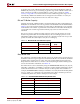
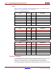
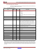
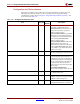
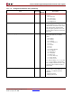
Table 2-16: Configuration and Status Ports (Continued)
Port Direction
Clock
Domain
Description