
User guide


40 www.xilinx.com Virtex-5 FPGA Integrated Endpoint Block
UG197 (v1.5) July 22, 2009
Chapter 2: Integrated Endpoint Block Functionality
R
Block RAM Interface
The Transmit (TX), Receive (RX), and Retry buffers are implemented with block RAM.
Each buffer has separate read and write interfaces. The sizes of the buffers can vary based
on the application’s needs.
• Transmit buffer. Buffers transmitted packets. It is divided into separate FIFOs for
posted, non-posted, and completion transactions (see Figure A-1, page 91 and
Table A-7, page 96).
• Receive buffer. Buffers received packets. It is divided into separate FIFOs for posted,
non-posted, and completion transactions (see Figure A-1, page 91 and Table A-7,
page 96).
• Retry buffer. Holds a copy of each TLP that is currently in the process of being
transmitted until the information has been received correctly (or it becomes clear that
the link has failed).
These three buffers are instantiated and configured by the Endpoint Block Plus Wrapper,
based on selections made in the CORE Generator GUI. Users implementing their design
with the Endpoint Block Plus Wrapper do not need to explicitly set any of the attributes or
connect any pins described in this section. The block RAM datapaths are 64 bits wide.
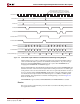
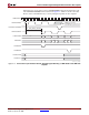
All three block RAM interfaces operate synchronously to the rest of the integrated
Endpoint block. Each interface has separate read and write addresses, data, and control
signals.
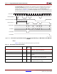
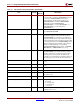
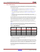
Table 2-8 shows the recommended aspect ratio for both ports of each dual-port block
RAM. The block RAM can be connected directly to the integrated Endpoint block using
fabric interconnect, without additional fabric logic.
Since the total amount of RAM used for the Retry buffer must always be a power of two,
the next size up is chosen when necessary. This restriction does not apply to the TX and RX
buffers, but choosing a size that is not a power of two might require additional fabric logic.
The CORE Generator tool always instantiates the TX and RX buffers as a power of two.
Block RAM output registers should generally be used but are not necessary if the design
can meet timing without them. The CORE Generator tool always uses the block RAM
output registers.
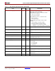
Table 2-8: Block RAM Sizing
RAM
Requirement
(KB) per Buffer
Number of
36K Block RAMs
Address Bits
Used
Aspect Ratio of
Each Block RAM
(no ECC
(1)
)
Block RAM Mode
4 1 [8:0] 512 x 64 Simple Dual Port
8 2 [9:0] 1k x 32 True Dual Port
16 4 [10:0] 2k x 16 True Dual Port
32 8 [11:0] 4k x 8 True Dual Port
64
(2)
16 [12:0] 8k x 4 True Dual Port
Notes:
1. If ECC is required, each block RAM must be 512 x 64. This block RAM requirement uses additional
fabric logic for all cases except when one 36K block RAM is used for a buffer. Fabric logic is always
required if the user wants ECC error counting or logging.
2. Not available for the Retry buffer.