
User guide


Virtex-5 FPGA Integrated Endpoint Block www.xilinx.com 37
UG197 (v1.5) July 22, 2009
Virtex-5 FPGA Integrated Endpoint Block Interface Descriptions
R
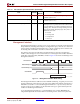
Management Interface
The Management interface is used to access various registers and signals in the integrated
Endpoint block, including the PCI Express Configuration Space, and various control and
status registers. The Management Interface also contains output signals for statistics and
monitoring and an interface to read flow control credit outputs.
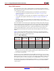
The interface has separate 32-bit data read and write buses. Separate read and write
enables control the type of access on the interface. For writes, byte-write enables determine
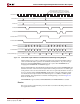
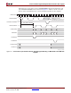
which byte of the 32-bit data (DWORD) is written. Figure 2-9 shows the read timing for the
Management interface.
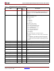
The Management Interface address bus has DWORD addressing. A typical processor bus
has byte addressing, where the lower two bits of the address bus indicate which byte in a
DWORD is accessed. To connect the Management Interface to a processor bus, the lower
two bits of the processor address are decoded with user logic to generate the byte write
enables for the Management Interface.
To use the Management interface to override attributes (for example,
DEVICEID), the
integrated Endpoint block must be held in reset during and for at least four cycles after
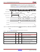
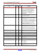
LLKRXCHNONPOSTEDAVAILABLEN[7:0]
Output user_clk Traffic classes with complete non-posted packets
available (active Low).
LLKRXCHCOMPLETIONAVAILABLEN[7:0]
Output user_clk Traffic classes with complete completion packets
available (active Low).
LLKRXPREFERREDTYPE[15:0]
Output user_clk Used with LLKRXCH*AVAILABLEN to determine
which queues have packets that can be read from the
associated FIFO in accordance with PCIe transaction
ordering rules. The bits are interpreted in pairs with
bits [1:0] allocated to TC0, bits [3:2] to TC1, and so on.
Within those two bits:
00: Posted
01: Non-posted
10: Completion
11: Reserved
Table 2-6: Transaction Layer Interface Ports (Continued)
Port Direction
Clock
Domain
Description
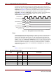
Figure 2-9: Management Interface Read Timing
CRMUSERCLK
MGMTADDR[10:0]
MGMTRDATA[31:0]
MGMTRDEN
A0
D0
D0 Can Be Read By User
UG197_c2_07_082406