
User guide

22 www.xilinx.com Virtex-5 FPGA Integrated Endpoint Block
UG197 (v1.5) July 22, 2009
Chapter 2: Integrated Endpoint Block Functionality
R
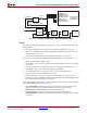
When the frequency of the user_clk domain is 250 MHz, there is no need to provide two
separate clocks to the integrated Endpoint block. In this case, the 250 MHz clock is tied to
all the core_clk ports and the user_clk ports must be tied High. This gives a very simple
timing model for the system: all signals on the integrated Endpoint block and all signals on
other blocks on the FPGA that directly interface with the integrated Endpoint block are
clocked by the same clock. These clock connections are included in the CORE Generator
wrappers.
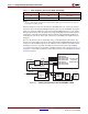
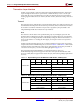
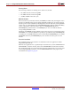
The core_clk and user_clk are obtained by using a Clock Management Tile (CMT). The
reference clock is brought on the device through the
CLKP and CLKN differential reference
clock pins to the RocketIO transceiver. The reference clock should be forwarded from the
RocketIO transceiver to the CMT. The CMT PLL must be used to derive the 250 MHz
core_clk from the reference clock (unless a 250 MHz reference clock is used). See Figure 2-3
and Figure 2-4. The CMT PLL, BUFGs, and clocking connections are included in the CORE
Generator wrappers.
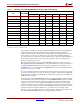
x4 250 125 or 250
x8 250 250
Notes:
1. The user_clk frequency is based on the configured lane width. It cannot be reduced, even when the
negotiated lane width is smaller.
Figure 2-3: Clocking for Applications with CLKDIVIDED = TRUE
Table 2-1: Clock Frequency Versus Lane Width (Continued)
Configured Lane Width core_clk Frequency (MHz) user_clk Frequency (MHz)
(1)
BUFG
BUFG
REFCLK
PLLLKDET
(100, 125, or 250 MHz)
GTP_DUAL
or
GTX_DUAL
Tile
REFCLK Frequency
core_clk (250 MHz)
BUFG
CMT
PLL
user_clk
(62.5 or 125 MHz)
Virtex-5 FPGA
Integrated
Endpoint Block
UG197_c2_09_081808
TX/RX
Block
RAMs
Retry
Block
RAMs
User
Logic
CRMCORECLK
CRMCORECLKRXO
CRMCORECLKTXO
CRMCORECLKDLO
CRMUSERCLK
CRMUSERCLKRXO
CRMUSERCLKTXO