
Installation guide

Kaleidescape Part No. 101-0105-00 Rev 3 Page 41
Kaleidescape Installation Guide Physical Installation
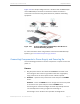
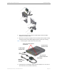
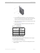
Figure 3-12 is a sample configuration for a 3U Server with an M500 Player
and an M300 Player connected to an Ethernet switch. The switch is
connected to the Internet using either wireless or powerline networking
equipment.
Figure 3-12 3U Server, M500 Player and M300 Player with Wireless or
Powerline Networking Equipment
For more information about using wireless connections for Kaleidescape
Systems, go to www.kaleidescape.com/go/wireless
.
Connecting Components to Power Supply and Powering On
Use the following procedure to connect components to a power source and
power on.
Servers
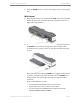
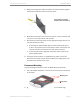
1. Plug the power cord into the socket labeled
AC-IN
on the back of the
server. Plug the other end into a grounded outlet with a high-quality
surge protector for the server power source. A UPS is optional.
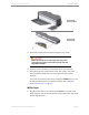
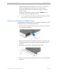
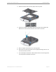
2. 3U Server — Open the front panel of the server and press the
POWER
button.
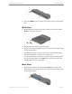
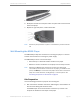
1U Server — Press the
POWER
button on the right side of the front panel
or remove the front panel and press the blue
POWER
button.
The blue lights on the disk cartridges illuminate sequentially and then
turn off briefly before turning on again and remaining on.
The blue light on the 3U Server hot spare disk cartridge blinks.
WAP or
Powerline adapter
Router
(if not integrated)
Internet
access device
Wireless bridge or
Powerline adapter
Ethernet switch
3U Server
M500 Player
M300 Player